Debugging system and debugging method for rail vehicle electronic equipment

A technology for electronic equipment and rail vehicles, which is applied in the field of rail transit and can solve problems such as complex debugging process

Pending Publication Date: 2021-04-27
CRRC QINGDAO SIFANG ROLLING STOCK RES INST
View PDF5 Cites 0 Cited by
  • Summary
  • Abstract
  • Description
  • Claims
  • Application Information

AI Technical Summary

Problems solved by technology

[0004] The present invention aims at the above-mentioned problems such as the complicated thread debugging process of the existing rail vehicle electronic equipment, and provides a debugging system and debugging method for rail vehicle electronic equipment with simple operation, low cost, high efficiency and reliability

Method used


Image

  • Debugging system and debugging method for rail vehicle electronic equipment
  • Debugging system and debugging method for rail vehicle electronic equipment

Examples


Embodiment 1

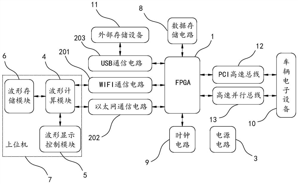
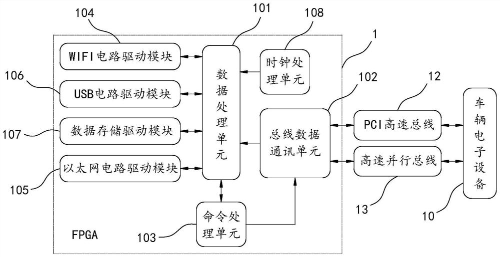
[0051] Embodiment 1: see figure 1 , 2 , a debugging system for rail vehicle electronic equipment, comprising:

[0052] FPGA1 is connected to the vehicle electronic device 10 to be debugged, and is used for data interaction with the vehicle electronic device 10 to be debugged;

[0053] The communication circuit is connected with FPGA1 and is used to transmit data inside FPGA1;

[0054] The power supply circuit 3 supplies power to the FPGA1 and the communication circuit and performs power management;

[0055] The waveform calculation module 4 calculates and analyzes the data transmitted by the communication circuit and converts it into a waveform;

[0056] The waveform display control module 5 is used to scale and selectively display the converted waveform;

[0057] The waveform storage module 6 is used for storing the converted waveform.

[0058] Specifically, the waveform calculation module calculates and analyzes the data it receives, and converts the data into waveforms...

Embodiment 2

[0083] Embodiment 2: a kind of debugging method that is used for rail vehicle electronic equipment, adopts the debugging system that is used for rail vehicle electronic equipment described in embodiment 1, and its specific steps are:

[0084] S1. Connect the electronic device board of the vehicle to be debugged with the debugging system through the PCI high-speed bus, and cache and manage the data inside the electronic device of the vehicle to be debugged through the bus data communication unit inside the FPGA. The connection mode between the electronic equipment board of the vehicle to be debugged and the debugging system is not limited to the PCI high-speed bus, but also can be connected through a high-speed parallel bus, or through two kinds of buses: a PCI high-speed bus and a high-speed parallel bus.

[0085] S2. Connect the upper computer to the communication circuit of the debugging system through WIFI or Ethernet, the upper computer sends command information to the data...


PUM


Abstract

The invention relates to a debugging system and debugging method for rail vehicle electronic equipment; the system comprises an FPGA which is used for the data interaction with to-be-debugged vehicle electronic equipment; a communication circuit which is connected with the FPGA and used for transmitting data in the FPGA; a power supply circuit which is used for supplying power to the FPGA and the communication circuit and managing the power supply; a waveform calculation module which is used for calculating and analyzing the data transmitted by the communication circuit and converting the data into waveforms; a waveform display control module which is used for zooming the converted waveform and selectively displaying the waveform; and a waveform storage module which is used for storing the converted waveform. The device is easy to operate, low in cost, efficient, reliable and good in portability.

Description

technical field [0001] The invention belongs to the technical field of rail transit, and relates to a debugging technology of rail vehicle electronic equipment, in particular to a debugging system and a debugging method for rail vehicle electronic equipment. Background technique [0002] With the rapid development of rail transit technology, people choose more subways, EMUs and high-speed rail for travel. While rail transit brings convenience to people, it also puts forward higher requirements for various electronic equipment of rail vehicles. Before the vehicle is operated with passengers, it is necessary to fully perform performance debugging on each electronic device to ensure its reliability and safety during the actual operation of the rail vehicle. [0003] Rail vehicles have a lot of electronic equipment, and usually electronic equipment has complex internal data. During the debugging process, it is often necessary to obtain internal data to determine whether the elec...

Claims


Application Information

Patent Timeline
Patent Type & Authority Applications(China)
IPC IPC(8): G01R31/00G01R13/00G05B19/042G06F11/273G06F13/38G06F13/42
CPCG01R31/008G01R13/00G05B19/0423G06F11/2733G06F13/385G06F13/4221G06F13/4282G06F2213/0042G06F2213/0024
Inventor 盖猛张小松潘德敏
Owner CRRC QINGDAO SIFANG ROLLING STOCK RES INST
Why Eureka
Try Eureka