
Feed flowing feeding device for aquaculture

An aquaculture and feed technology, applied in applications, fish farming, motor vehicles, etc., can solve problems such as low efficiency and labor consumption

Pending Publication Date: 2021-04-30
安徽省黄雀畈现代农业开发有限公司
View PDF1 Cites 0 Cited by
  • Summary
  • Abstract
  • Description
  • Claims
  • Application Information

AI Technical Summary

Problems solved by technology

[0005] The purpose of the present invention is to solve the problems of labor-intensive a

Method used

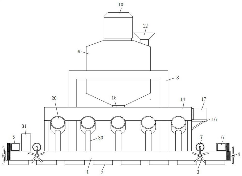
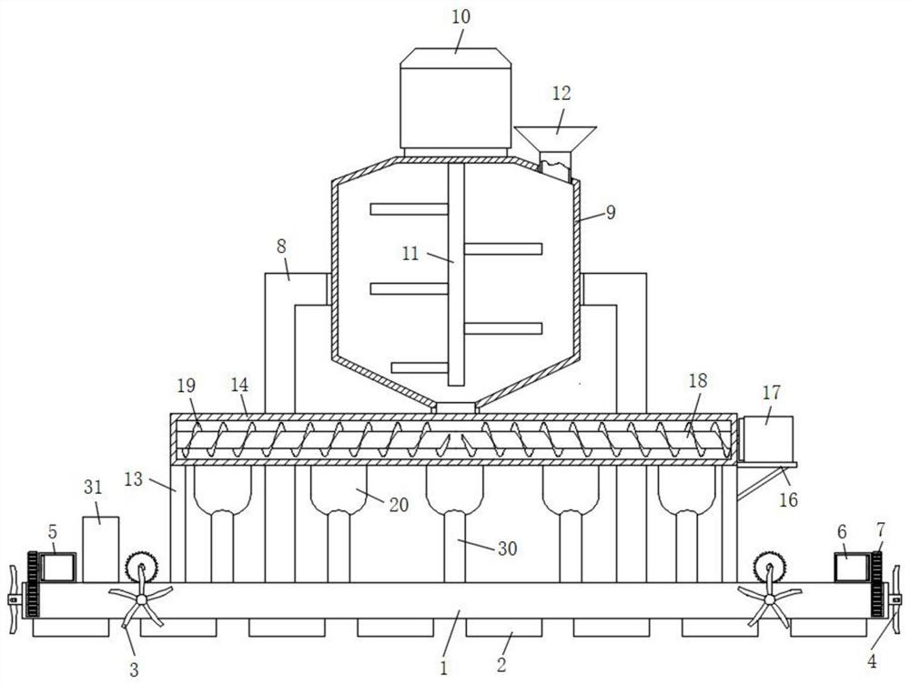
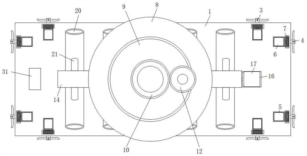

Image

  • Feed flowing feeding device for aquaculture
  • Feed flowing feeding device for aquaculture
  • Feed flowing feeding device for aquaculture

Examples


Example Embodiment

[0030] Example 1

[0031] refer to Figure 1-5A feed flow feeding device for aquaculture comprises a base 1, a suspension block 2 is fixedly connected to the bottom surface of the base 1, a reversing propeller 3 is rotatably installed at the front and rear ends of the base 1, and a propeller 4 is rotatably installed on both side walls of the base 1 , the upper ends of the reversing propeller 3 and the propulsion propeller 4 are provided with a sealing box 5 near the center of the base 1. The inner bottom surface of the sealing box 5 is fixed with a servo motor 6 through screws. The output end of the servo motor 6 is connected to the reversing The propeller 3 and the propeller 4 are connected by rotation through the gear set 7, and a mounting frame 8 is also welded at the center of the top surface of the base 1. The center of the top surface of the mounting frame 8 is provided with a cylindrical groove, and the inner wall of the cylindrical groove is fixed by screws. The mater...

Example Embodiment

[0033] Embodiment 2

[0034] like Figure 4 As shown, this embodiment is basically the same as Embodiment 1. Preferably, the lower end of the ejection sheet 27 is also fixedly connected to a limiting plate 32 on the side close to the center of the base 1 , and the limiting plate 32 is slidably connected to the side wall of the ejection barrel 20 .

[0035] In this embodiment, a limiting plate 32 is also slidably connected between the lower end of the ejection piece 27 and the side wall of the ejection material cylinder 20 , so that the ejection piece 27 is more stable when ejected.

Example Embodiment

[0036] Embodiment 3

[0037] like Figure 1-4 As shown, this embodiment is basically the same as Embodiment 1. Preferably, the output end of the receiver 31 is electrically connected to the control end of the servo motor one 6, the servo motor two 10, the servo motor three 17 and the servo motor four 25, and is electrically connected with the control terminal of the servo motor one 6, the servo motor two 10, the servo motor three 17 and the servo motor four 25 The receiver 31 is also equipped with a remote controller, and a wireless connection is adopted between the remote controller and the receiver 31 .

[0038] In this embodiment, the receiver 31 is also equipped with a remote controller, and the remote controller and the receiver 31 are connected wirelessly, which facilitates the forward, backward and reverse operations of the control device, and greatly improves the stability of the device operation.


PUM


Abstract

The invention discloses a feed flowing feeding device for aquaculture. The feed flowing feeding device comprises a base, suspension blocks are fixedly connected to the bottom surface of the base, reversing propellers are rotatably mounted at the front end and the rear end of the base respectively, propelling propellers are rotatably mounted on the two side walls of the base, sealing boxes are arranged on the sides, close to the center of the base, of the upper ends of the reversing propellers and the propelling propellers, first servo motors are fixedly connected to the inner bottom surfaces of the sealing boxes through screws, the output ends of the first servo motors are rotationally connected with the reversing propellers and the propelling propellers through gear sets, a mounting frame is further welded to the center of the top surface of the base, a cylindrical groove is formed in the center of the top surface of the mounting frame, and a mixing barrel is fixedly connected to the inner wall of the cylindrical groove through screws. The feed flowing feeding device is reasonable in design, stable in operation and capable of achieving flowing feeding operation of feed during aquaculture, so that the feeding range of the feed is enlarged, the requirement for uniform feeding of fish fries is met, and certain guarantee is provided for high-quality aquaculture.

Description

technical field [0001] The invention relates to the technical field of aquaculture auxiliary equipment, in particular to a feed flow feeding device for aquaculture. Background technique [0002] Aquaculture is the use of waters available for breeding by humans. According to the ecological habits of the breeding objects and the requirements for the environmental conditions of the waters, aquaculture technology and facilities are used to engage in aquatic economic animal and plant breeding. It is one of the agricultural production sectors. [0003] After searching, the patent with application number 201910596076.8 discloses a feed feeding device for aquaculture, which includes a hull and a storage box, and a storage cavity is arranged inside the storage box; it also includes a fixing plate, a ball bearing, a threaded pipe, a threaded rod, The support plate, four sets of inserting plates, feed pipe, discharge pipe, hopper and flow regulating valve, the fixed plate is installed ...

Claims


Application Information

Patent Timeline
IPC IPC(8): A01K61/80B63B35/00B63H1/14B63H25/42
CPCA01K61/80B63B35/00B63H1/14B63H25/42Y02A40/81
Inventor 侯长旺宋泽君冯江华
Owner 安徽省黄雀畈现代农业开发有限公司
Learn More