Gripper device of precision mold manufacturing robot
A robot gripper and precision mold technology, applied in the field of precision mold manufacturing, can solve the problem of low flexibility and achieve the effects of high flexibility, enhanced grip and stability, and enhanced movement stability
- Summary
- Abstract
- Description
- Claims
- Application Information
AI Technical Summary
Problems solved by technology
Method used
Image

Examples
Embodiment 1
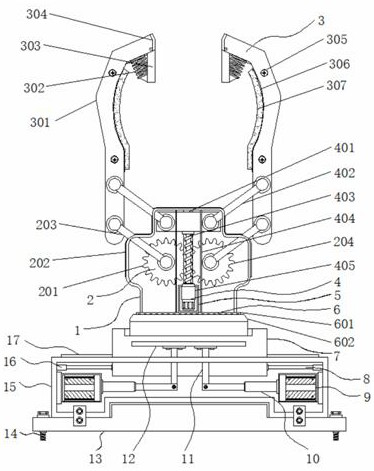
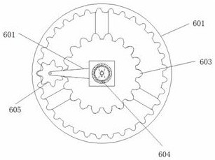
[0035] Example 1: See Figure 1-6 , a precision mold manufacturing robot gripper device, including a housing 1 and a moving block 7, the bottom end of the housing 1 is provided with a moving block 7, a rotating mechanism 6 is arranged between the housing 1 and the moving block 7, the housing 1 The bottom end of the interior is provided with a fixed frame 5, the interior of the housing 1 is provided with a drive mechanism 4, the two ends of the interior of the housing 1 are provided with a stable opening and closing structure 2, the top of the housing 1 is provided with a clamping structure 3, and the moving block The bottom end of 7 is provided with a moving mechanism;
[0036] see Figure 1-6 , a precision mold manufacturing robot gripper device also includes a moving mechanism, the moving mechanism includes a mounting base 13, the mounting base 13 is arranged below the moving block 7, the two sides of the mounting base 13 are provided with mounting bolts 14, and the top of ...
Embodiment 2
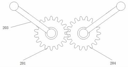
[0039] Embodiment 2: The stable opening and closing structure 2 is composed of a first gear 201, a through groove 202, a pull-down rod 203, and a second gear 204. The first gear 201 is arranged on one side of both ends of the housing 1, and the second gear 204 is arranged on the On the other side of the two ends inside the housing 1, the first gear 201 and the second gear 204 mesh with each other, and one end of the first gear 201 and the second gear 204 is respectively hinged with a pull-down rod 203, and the through groove 202 is arranged on the outside of the housing 1. On the top and both sides, the pull-down rod 203 passes through the through groove 202 and extends to the outside of the housing 1;
[0040] The first gear 201 and the second gear 204 have the same size, the pull-down rod 203 is provided with four groups, the first gear 201 and the second gear 204 are respectively provided with two groups and are symmetrically distributed about the vertical center line of the...
Embodiment 3
[0042] Embodiment 3: The clamping structure 3 is composed of a clamping hand 301, a spring 302, a splint 303, a friction part 304, a fixing screw 305, a slot 306 and a gasket 307. The clamping hand 301 is provided with two groups at the top of the housing 1, Friction parts 304 are respectively arranged on the top of gripper 301, splint 303 is hinged at the bottom of friction part 304, and spring 302 is fixedly connected between splint 303 and gripper 301, and the inner side of gripper 301 is provided with slot 306, and slot 306 A gasket 307 is embedded inside, and a fixing screw 305 is fixedly connected between the gasket 307 and the gripper 301;
[0043] The bottom ends of the grippers 301 are respectively hinged with the pull-down rods 203, the splint 303 is hook-shaped, and the intermediate position between the gasket 307 and the grippers 301 is arc-shaped;
[0044] Specifically, such as figure 1 with Figure 4 As shown, when clamping a precision mold with a specific shap...
PUM
 Abstract
Description
Claims
Application Information