
A gantry line pcb board electroplating hanging board fixture

A technology of PCB board and gantry line, which is applied in the field of gantry line PCB board electroplating and hanging fixtures, which can solve the problems of unable to automatically center the PCB circuit board and increase the work intensity of the operator.

Active Publication Date: 2021-12-21
广东成功自动化设备有限公司
View PDF0 Cites 0 Cited by
  • Summary
  • Abstract
  • Description
  • Claims
  • Application Information

AI Technical Summary

Problems solved by technology

[0004] The embodiment of the present invention provides a gantry line PCB plate electroplating hanging board fixture to solve the problem that the hanging board fixture in the prior art cannot automatically center the PCB circuit board, resulting in that the hanging board fixture clamps the PCB circuit board every time Manual centering is required, a technical problem that increases the work intensity of the operator

Method used


Image

  • A gantry line pcb board electroplating hanging board fixture
  • A gantry line pcb board electroplating hanging board fixture
  • A gantry line pcb board electroplating hanging board fixture

Examples


Embodiment Construction

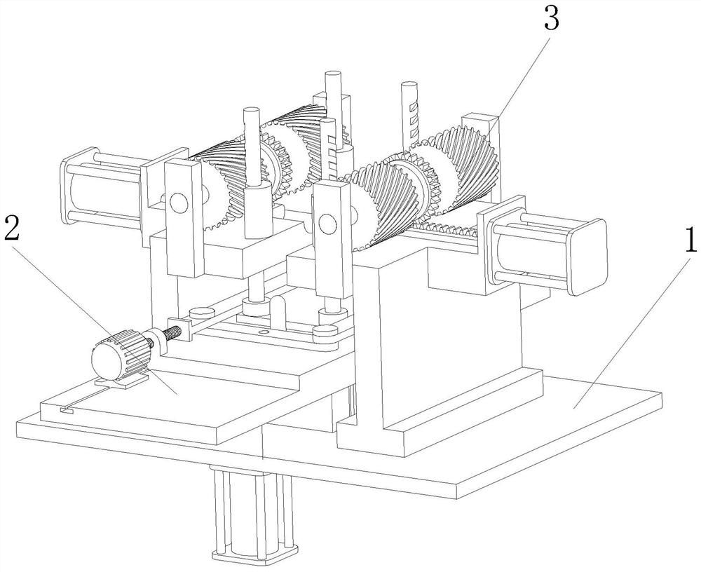
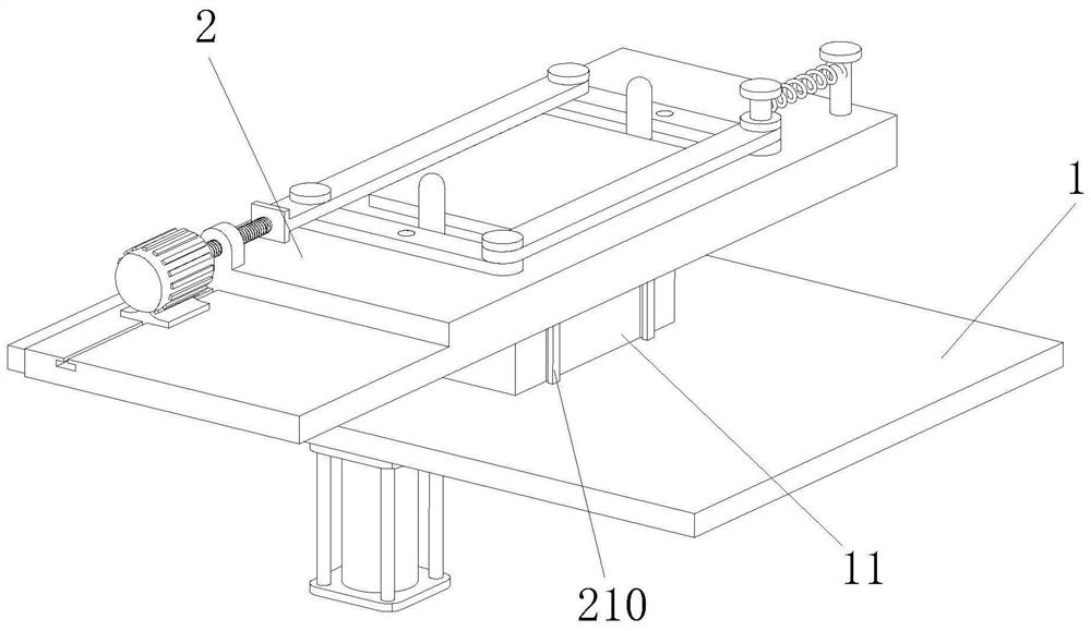
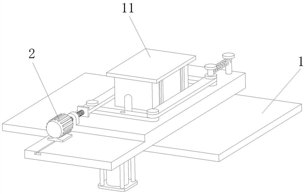
[0027] In order to make the purpose, technical solution and advantages of the present invention clearer, the technical solution of the present invention will be clearly and completely described below in conjunction with specific embodiments of the present invention and corresponding drawings. Apparently, the described embodiments are only some of the embodiments of the present invention, but not all of them. Based on the embodiments of the present invention, all other embodiments obtained by persons of ordinary skill in the art without making creative efforts belong to the protection scope of the present invention.

[0028] The technical solutions provided by various embodiments of the present invention will be described in detail below in conjunction with the accompanying drawings.

[0029]The embodiment of the present invention provides a fixture for electroplating and hanging boards of gantry line PCB board parts, including a workbench 1, a centering part 2 and a clamping p...


PUM


Abstract

The invention discloses a gantry line PCB plate electroplating hanging board fixture, which belongs to the technical field of printed circuit boards, and includes a workbench, a centering part and a clamping part arranged on the workbench, and the centering part is arranged on the workbench The top of the centering part, the clamping part is provided with two groups, and the two groups of clamping parts are respectively arranged on the top of the workbench and on the left and right sides of the centering part, and the centering part includes a centering bottom plate, a first centering rod , the second centering rod, the centering cross bar and the centering column. When working, place the PCB board on the top of the centering bottom plate and between the two centering columns. At this time, push the first centering rod backward , the rectangle formed by the first centering rod, the second centering rod and the two centering cross bars is gradually deformed into a parallelogram, so that the distance between the first centering rod and the second centering rod is gradually reduce, so that the PCB board is clamped by the first centering rod and the second centering rod, and then the centering of the PCB board is realized by limiting the position of the two centering posts.

Description

technical field [0001] The invention relates to the technical field of printed circuit boards, in particular to a jig for electroplating and hanging boards of gantry line PCB board parts. Background technique [0002] Electronic devices refer to devices made by utilizing and controlling the movement of electrons in vacuum, gas or solid. They are divided into electric vacuum devices, gas-filled tube devices and solid-state electronic devices. They are used for rectification, amplification, modulation and oscillation in analog circuits. , frequency conversion, phase lock, control, correlation and other functions. [0003] However, most of the existing electronic devices need PCB circuit boards to carry the electrical components inside. The PCB circuit boards need to be electroplated during the production process. Most of the electronic devices are clamped by electroplating hanging board fixtures during electroplating. The existing electroplating When clamping the electroplate...

Claims


Application Information

Patent Timeline
Patent Type & Authority Patents(China)
IPC IPC(8): C25D17/06C25D7/00H05K3/00H05K3/18
CPCC25D17/06C25D7/00H05K3/188H05K3/0008
Inventor 吴昱凯梁飞戴彬乔文举余仁水
Owner 广东成功自动化设备有限公司
Learn More