Eureka AIR delivers breakthrough ideas for toughest innovation challenges, trusted by R&D personnel around the world.

Roof communication base station supporting structure

A communication base station and support structure technology, which is applied in the field of base station support structures, can solve problems such as poor support structure effect, complex structure, and inconvenient maintenance, and achieve the effects of poor solution effect, flexible adjustment, and prevention of poor communication signals

Inactive Publication Date: 2021-04-30
中宏航天(北京)技术有限公司
View PDF2 Cites 0 Cited by
  • Summary
  • Abstract
  • Description
  • Claims
  • Application Information

AI Technical Summary

Problems solved by technology

[0003] In view of the above situation, in order to overcome the defects of the prior art, the present invention provides a support structure for a communication base station on the roof, which adopts a combination of height and multiple angle adjustments, and realizes efficient fixing of the support structure while realizing adjustment of height and angle. The technical effect of flexible adjustment further enhances the communication effect of the communication base station, and adopts the method of snapping, rotating and elastically pulling to realize the effect of elastically pulling and limiting the base station, preventing the communication signal of the base station from being poor due to wind jitter, and effectively solving the problem. At present, the support structure of the roof communication base station in the market is poor, and its own structure is complex, and the maintenance is relatively inconvenient.

Method used


Image

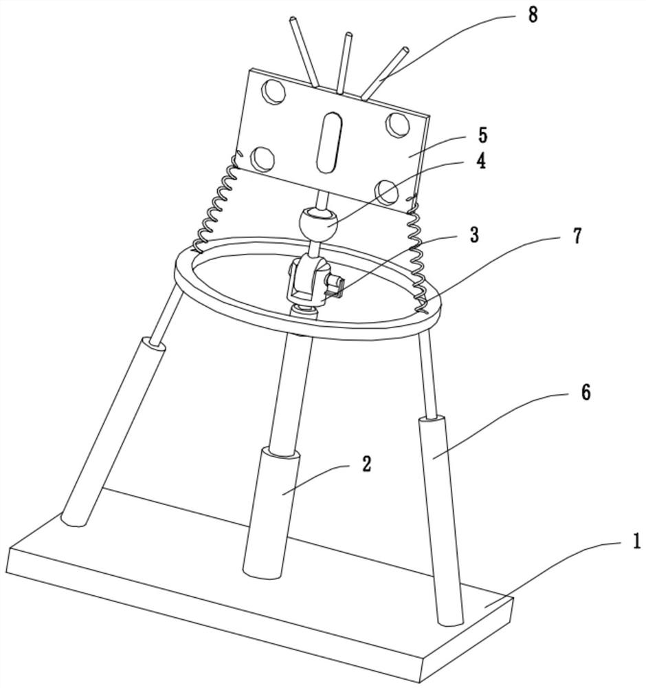
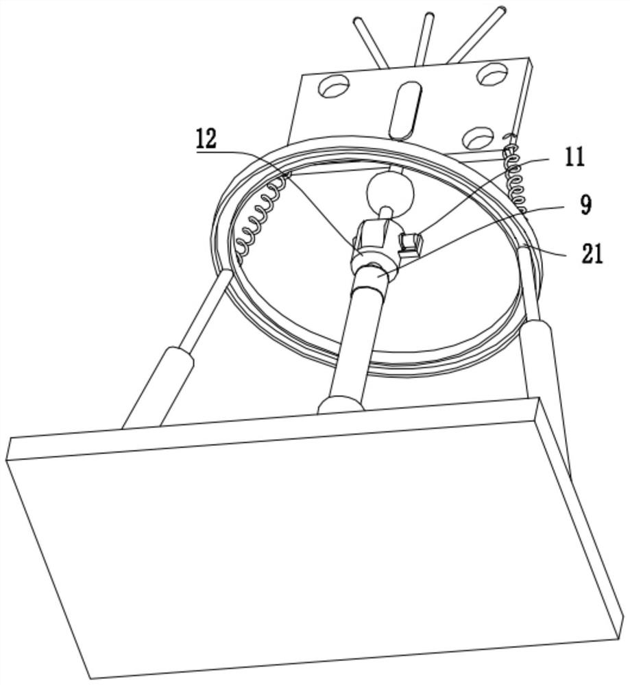
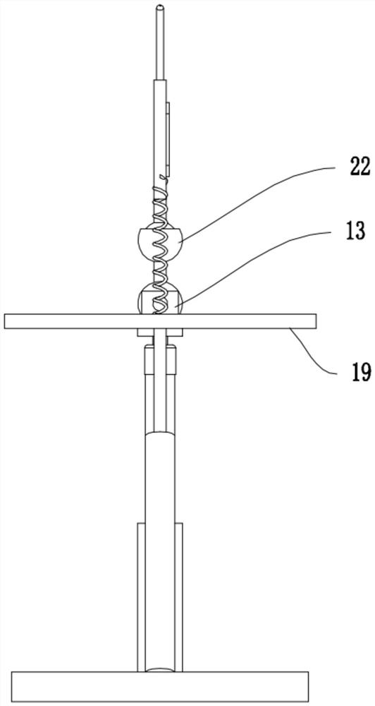
  • Roof communication base station supporting structure
  • Roof communication base station supporting structure
  • Roof communication base station supporting structure

Examples


Embodiment Construction

[0019] The technical solutions in the embodiments of the present invention will be clearly and completely described below in conjunction with the accompanying drawings in the embodiments of the present invention. Obviously, the described embodiments are only some of the embodiments of the present invention, not all of them; based on The embodiments of the present invention and all other embodiments obtained by persons of ordinary skill in the art without making creative efforts belong to the protection scope of the present invention.

[0020] Such as Figure 1-6 As shown, the support structure of the communication base station on the roof of the present invention includes a support base plate 1, a height adjustment member 2, a rotary angle adjustment device 3, a universal rotation adjustment device 4, an installation fixing plate 5, a follow-up telescopic support member 6, a snap-in Rotary elastic pulling device 7 and lightning rod 8, the height adjustment member 2 is arranged...


PUM


Abstract

The invention discloses a roof communication base station supporting structure. The roof communication base station supporting structure comprises a supporting bottom plate, a height adjusting piece, a rotary angle adjusting device, a universal rotation adjusting device, a mounting fixing plate, a follow-up telescopic supporting piece, a clamping rotary elastic pulling device and a lightning rod. The invention belongs to the technical field of base station supporting structures, and particularly relates to the roof communication base station supporting structure. The mode of combining height adjustment and various angle adjustment is adopted, the technical effect of flexibly adjusting the height and the angle while efficiently fixing the supporting structure is achieved, and the communication effect of a communication base station is further enhanced; and the mode of clamping rotary elastic pulling is adopted, the effect of elastic pulling limiting of the base station is achieved, the situation that communication signals of the base station are poor due to wind power shaking is prevented, and the problems that roof communication base station supporting structures in the current market are poor in effect, complex in structure and inconvenient to maintain are effectively solved.

Description

technical field [0001] The invention belongs to the technical field of base station support structures, and specifically refers to a support structure for a communication base station on a roof. Background technique [0002] The roof communication base station is a kind of fixed device that facilitates the mobile communication switching center and the radio transceiver station for information transmission between the mobile phone terminal, so as to achieve good signal reception, while the existing communication from the roof The structure of the base station is often too simple, which leads to the fact that the staff need to carry a lot of preparation tools to complete the installation of the plate antenna during the installation process of the plate antenna. The entire base station installation process can only be completed with assistance, which leads to a very time-consuming, labor-intensive and complicated process for the entire base station installation process. Conte...

Claims


Application Information

Patent Timeline
IPC IPC(8): E04H12/00E04H12/18E04H12/20
CPCE04H12/00E04H12/182E04H12/187E04H12/20
Inventor 刘霖
Owner 中宏航天(北京)技术有限公司
Why Eureka
Eureka Blog
Learn More