Mechanical booster cylinder punching device

A punching device and a force-increasing technology, applied in the field of cylinder punching devices, can solve the problems of large cylinder volume, large demand for public air sources, and high cost

Inactive Publication Date: 2017-11-10
ANHUI JIANGHUAI AUTOMOBILE GRP CORP LTD
View PDF5 Cites 0 Cited by
  • Summary
  • Abstract
  • Description
  • Claims
  • Application Information

AI Technical Summary

Problems solved by technology

[0003] The disadvantages of the existing technology are that it cannot provide greater punching force, and can only punch holes in thin plates; the volume of the cylinder is large, and the volume of the device is large; the demand for public air sources is greater, and the cost is high

Method used


Image

  • Mechanical booster cylinder punching device
  • Mechanical booster cylinder punching device
  • Mechanical booster cylinder punching device

Examples


Embodiment Construction

[0018] Embodiments of the present invention are described in detail below, examples of which are shown in the drawings, wherein the same or similar reference numerals designate the same or similar elements or elements having the same or similar functions throughout. The embodiments described below by referring to the figures are exemplary only for explaining the present invention and should not be construed as limiting the present invention.

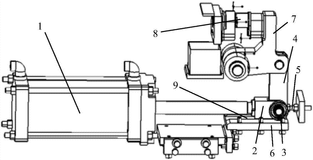
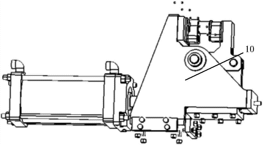
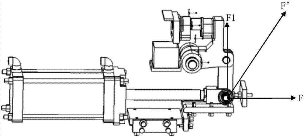
[0019] figure 1 It is the perspective view of the punching device of the mechanical booster cylinder in the present invention, figure 2 It is the installation schematic diagram of the punching device of the mechanical booster cylinder in the present invention, image 3 It is the boost principle diagram of the mechanical boost cylinder punching device in the present invention, Figure 4 It is the force principle diagram of the punching device of the mechanical booster cylinder in the present invention.

[0020] Refer to attached Fig...


PUM


Abstract

The invention discloses a mechanical booster cylinder punching device. The device comprises a cylinder, a cylinder pushing head, a deep groove ball bearing, a connecting rod, a limiting nut, a groove booster plate, a clamp arm, a punching mechanism, a guide groove and a booster mechanism bracket. The device can amplify the force finally reflected on a punch by 4-5 times under the condition of equal size of the cylinder, realizes punching of a high-torque plate, can obviously reduce the size of the cylinder to reduce the size of a blanking device, and saves public energy.

Description

technical field [0001] The invention relates to a cylinder punching device, in particular to a punching device for a mechanical booster cylinder. Background technique [0002] The cylinder punching device uses the cylinder as the power source to drive the punch mechanism to move, and is often used as a device for punching plates. The pneumatic system has the advantages of simple structure, low cost, safety and reliability, and no pollution. The punching of the plate also uses the cylinder as the power source, but the cylinder punching device in the prior art is mostly limited to the Sheet metal punching. If you need to provide greater punching force, you need a larger diameter cylinder or replace other forms as a power source, such as hydraulic pressure. [0003] The disadvantages of the prior art are that it cannot provide greater punching force, and can only punch thin plates; the volume of the cylinder is large, and the volume of the device is large; the demand for a pu...

Claims


Application Information

Patent Timeline
Patent Type & Authority Applications(China)
IPC IPC(8): B21D28/26
CPCB21D28/26
Inventor 刘春利李雪莲杨兆虎郑子涛
Owner ANHUI JIANGHUAI AUTOMOBILE GRP CORP LTD
Why Eureka
Try Eureka