A flexible resistance welding device for thermoplastic composite materials

A composite material and resistance welding technology, which is applied in the direction of household appliances, other household appliances, household components, etc., can solve problems such as uneven current density, overheating of composite materials, and difficulty in handling welding work, so as to ensure welding quality and stability , Ensure the accuracy of the installation position, improve the effect of welding stability

Active Publication Date: 2020-12-11
CIVIL AVIATION UNIV OF CHINA
View PDF3 Cites 0 Cited by
  • Summary
  • Abstract
  • Description
  • Claims
  • Application Information

AI Technical Summary

Problems solved by technology

However, the material to be welded is only fixed on the welding platform by the strip pressure plate, which cannot guarantee the stability of the welding electrode contact
At the same time, the copper block electrodes cannot be accurately positioned and installed, which leads to uneven current density and local overheating of the composite material, which affects the mechanical properties of the welded joints
He Zhenpeng and Wang Hongyang designed a simple mechanical thermoplastic composite welding device, which can manually adjust the vertical height of the welding platen and the clamping width of the welded part, but the welding electrode uses an integrated double-layer copper plate, so that the electrode contact area cannot be adjusted. Therefore, it is difficult to deal with the welding work of joints of different sizes, and can only complete the task of static resistance welding, and cannot realize dynamic welding
[0004] To sum up, the existing thermoplastic composite resistance welding devices still lack the flexible adjustment ability of process parameters and clamping tooling, resulting in poor quality and lack of stability of thermoplastic composite resistance welding joints

Method used


Image

  • A flexible resistance welding device for thermoplastic composite materials
  • A flexible resistance welding device for thermoplastic composite materials
  • A flexible resistance welding device for thermoplastic composite materials

Examples


Embodiment Construction

[0025] The structure of the present invention will be further described below in conjunction with the accompanying drawings and through embodiments. It should be noted that this embodiment is illustrative rather than limiting.

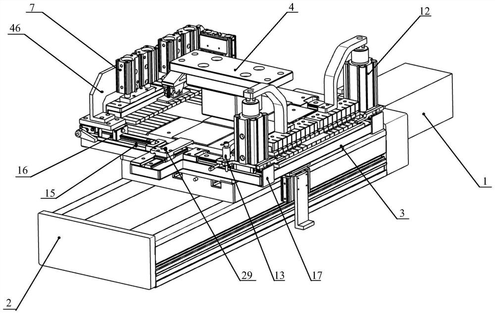
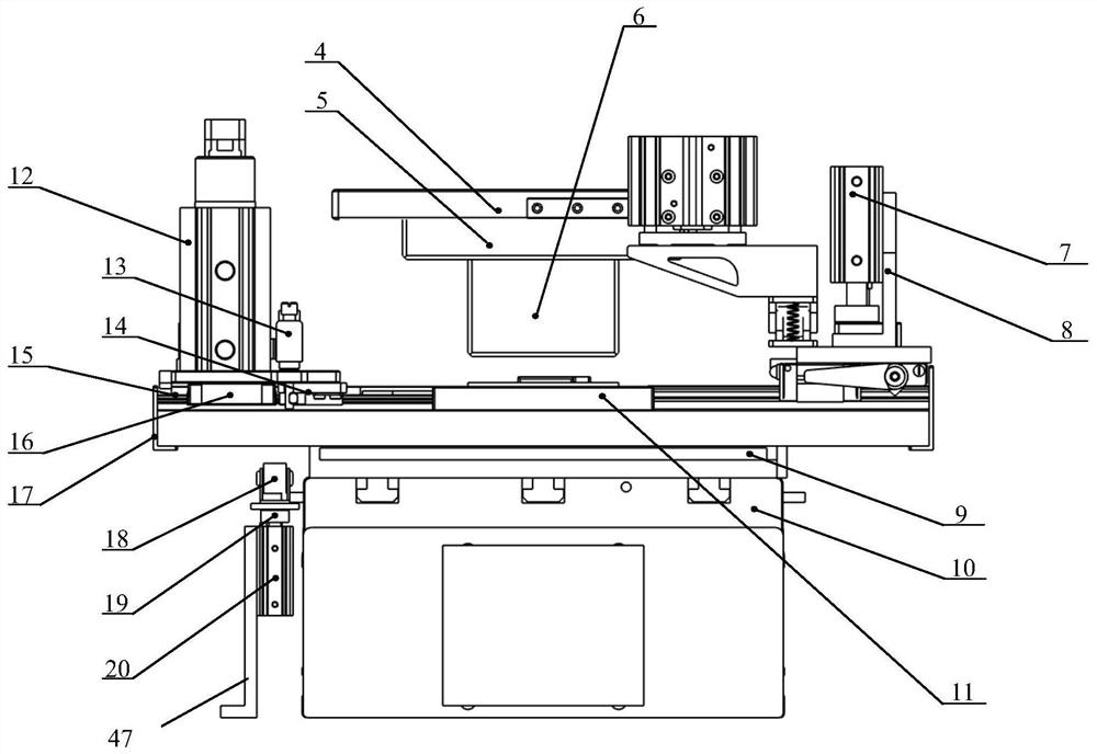
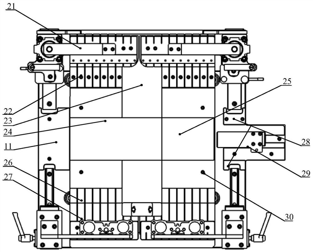
[0026] like Figure 1 to Figure 5 As shown, the thermoplastic composite flexible resistance welding device provided by the present invention includes a servo drive motor 1, a precision ball guide linear motion system 2 and a thermoplastic composite resistance welding platform 3; wherein the precision ball guide linear motion system 2 is a cuboid structure, and the top A track is provided along the length direction, and the power output is provided by the servo drive motor 1; the thermoplastic composite material resistance welding platform 3 is installed on the precision ball guide linear motion system 2 in a manner that can move along the upper track of the precision ball guide linear motion system 2.

[0027] The thermoplastic composite material resi...


PUM


Abstract

The invention discloses a thermal plastic composite material flexible resistance welding device. The device comprises a servo driving motor, a precision roller guiding rail linear movement system anda thermal plastic composite material resistance welding platform, wherein the precision roller guiding rail linear movement system is of a rectangular structure, the top face is provided with a rack in the length direction, and power output is provided by the servo driving motor; the thermal plastic composite material resistance welding platform can be installed on the precision roller guiding rail linear movement system by moving along the rail on the precision roller guiding rail linear movement system. The device has the advantages that welding lower pressure is provided through the servo pressure system, a to-be-welded part is positioned and resistance heating are conducted by a key type flexible electrode module, welding current is guided by connecting the electrode module, and therefore the purpose of thermal plastic composite material static and continuous dynamic flexible resistance welding is achieved.

Description

technical field [0001] The invention belongs to the technical field of composite material connection, in particular to a thermoplastic composite material flexible resistance welding device. Background technique [0002] With the development of advanced thermoplastic composite material preparation technology and the reduction of manufacturing cost, a variety of high-performance thermoplastic composite materials have been tried on foreign models, such as Gulfstream V rudder rib and leading edge, Airbus A380 aileron wing rib and elevator auxiliary For parts such as wing ribs, the new wing leading edge skin and rib connection method used on Airbus A340 and A380 models adopts advanced thermoplastic composite material welding technology, which can avoid the structural increase caused by traditional mechanical riveting technology. The problem of weight and stress concentration at the joint can be shortened, and the process cycle of the bonding technology can be shortened and the re...

Claims


Application Information

Patent Timeline
Patent Type & Authority Patents(China)
IPC IPC(8): B29C65/18B29L31/30
Inventor 王志平马梁路鹏程
Owner CIVIL AVIATION UNIV OF CHINA
Why Eureka
Try Eureka