Tungsten electrode-consuming electrode indirect electric arc welding device and its welding method

A welding method and melting electrode welding technology, applied in arc welding equipment, welding equipment, manufacturing tools, etc., can solve the problems of high dilution rate, large heat input of workpiece base material, low weld deposition rate, etc., and achieve improved Effects of melting speed, reducing weld dilution rate, and increasing deposition rate

Inactive Publication Date: 2008-09-17
HARBIN INST OF TECH
View PDF0 Cites 28 Cited by
  • Summary
  • Abstract
  • Description
  • Claims
  • Application Information

AI Technical Summary

Problems solved by technology

[0003] The purpose of the present invention is to solve the problems that the traditional arc welding connects the base metal of the workpiece to the power source, the heat input of the base metal of the workpiece is large, the welding seam deposition rate is low, and the dilution rate is high, and a tungsten electrode-melting electrode indirect arc welding is designed. device and its welding method

Method used


Image

  • Tungsten electrode-consuming electrode indirect electric arc welding device and its welding method
  • Tungsten electrode-consuming electrode indirect electric arc welding device and its welding method
  • Tungsten electrode-consuming electrode indirect electric arc welding device and its welding method

Examples


specific Embodiment approach 1

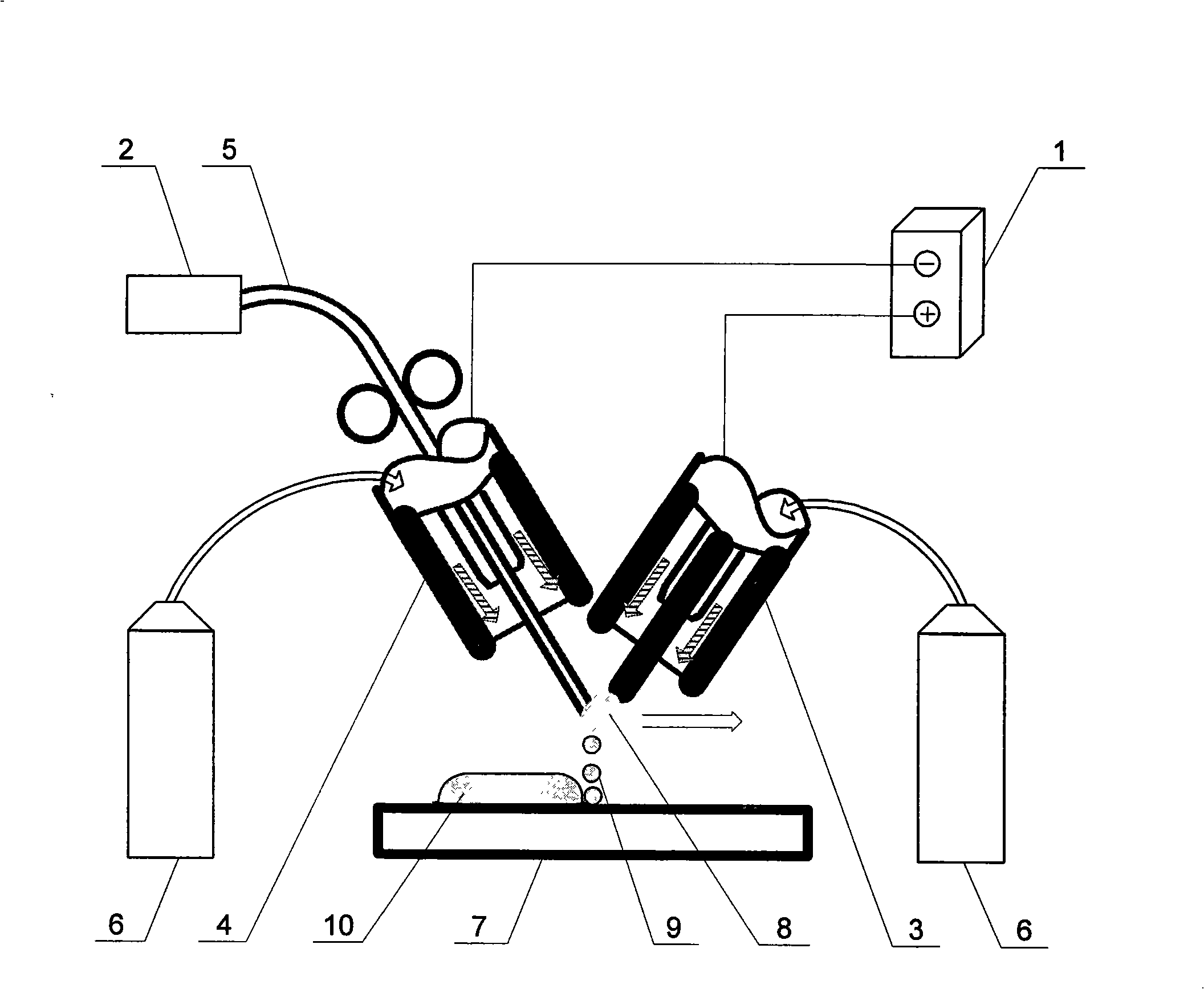
[0019] Specific implementation mode one: the following combination figure 1 Describe this embodiment, this embodiment is made up of GTAW power supply 1, wire feeder 2, tungsten electrode welding torch 3, melting pole welding torch 4, welding wire 5 and shielding gas cylinder 6, and wire feeder 2 is connected with one end of welding wire 5, and welding wire 5 The other end of the tungsten electrode welding torch 3 and the melting electrode welding torch 4 are connected to the positive and negative terminals of the GTAW power supply 1 respectively. The intersection of the axes of the tungsten electrode welding torch 3 and the melting electrode welding torch 4 is located above the workpiece to be welded, and the gas output ends of the two shielding gas cylinders 6 communicate with the shielding gas inlets of the tungsten electrode welding torch 3 and the melting electrode welding torch 4 respectively.

specific Embodiment approach 2

[0020] Specific embodiment two: this embodiment is a welding method implemented based on the device of embodiment one, and the welding steps are as follows:

[0021] Step 1: Process the part to be welded of the workpiece 7 into grooves, curls or no processing as required;

[0022] Step 2: Fix the workpiece 7 on the fixture to be welded;

[0023] Step 3: Keep the included angle between the tungsten welding torch 3 and the melting electrode torch 4 between 30°-90°; the distance between the tip end of the tungsten electrode of the tungsten welding torch 3 and the end of the welding wire 5 is between 2mm-5mm ; The distance between the intersection of the axes of the two welding torches and the surface of the workpiece 7 is 5mm-16mm;

[0024] Step 4: Set the process parameters, the welding current is between 20A-180A; the wire feeding speed is between 2.0m / min-12m / min; the gas flow rate of the tungsten welding torch 3 is between 10L / min-20L / min; The gas flow rate of the melting e...

specific Embodiment approach 3

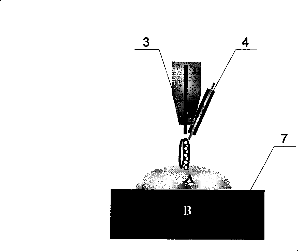
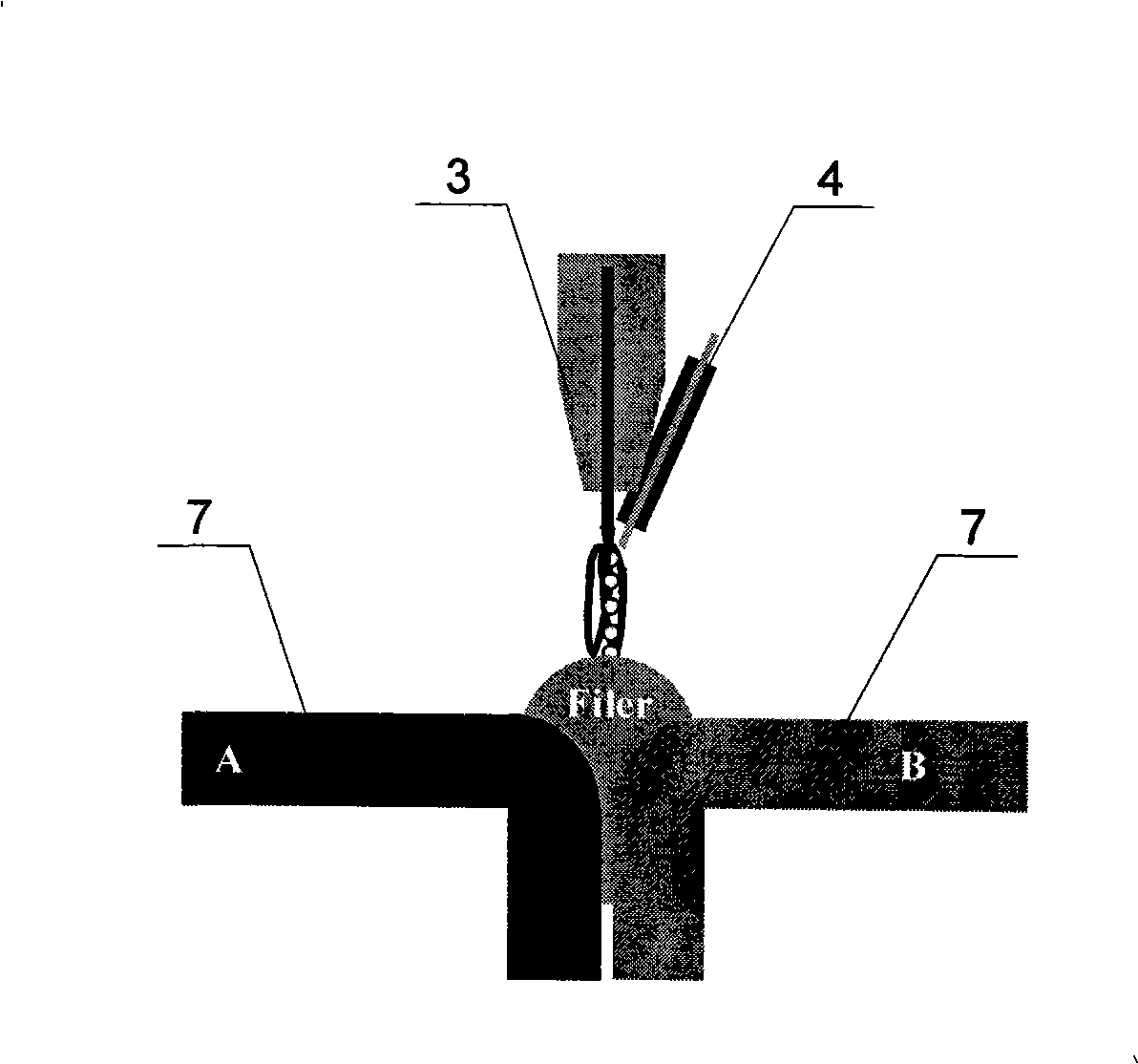
[0026] Specific embodiment three: provide a specific embodiment, weld with the method of the present invention, as figure 2 shown. The process is as follows: the workpiece 7 used is 30CrMnSi structural steel with a thickness of 3 mm, the composition of the welding wire 5 is CuSi3Mn, and the diameter of the welding wire 5 is 1.0 mm. Use a stainless steel brush to polish the surface of the part to be welded of the workpiece 7 to remove rust. A special fixture is used to position the workpiece 7 . Use acetone to clean the workpiece 7, remove oil stains and impurities, and wait for welding after drying. Connect the tungsten electrode welding torch 3 and the melting electrode welding torch 4 to the positive and negative poles of the GTAW power supply 1 respectively, keep the angle between the two welding torches at 45°, the distance between the tip of the tungsten electrode welding torch 3 and the welding wire 5 is 4mm, and the intersection point of the axes of the two welding t...


PUM

PropertyMeasurementUnit
lengthaaaaaaaaaa
diameteraaaaaaaaaa
diameteraaaaaaaaaa

Abstract

The invention relates to an indirect arc welding device between tungsten electrode and melting electrode and a welding method thereof, belonging to the technical field of material welding device and welding method, which is used to solve the problems in the prior arc welding devices, such as high hot input, low weld joint deposited ratio and high dilution ratio. The two ends of the welding wire are respectively connected with a wire feeder and a melting electrode welding torch, and exposed outside of the conductive mouth of the melting electrode welding torch. The welding wire is connected with a power supply, and the tungsten electrode welding torch and the melting electrode welding torch are connected respectively with the positive and negative electrodes of GTAW, and the axial point of the two welding torches is on the top of the weldment to be welded, and two protection gas cylinders are connected respectively with the protection gas inlets. Based on the device to weld in a certain welding process, turning on the arc generating switch, and using arc only generated between the tungsten electrode and melting electrode to quickly heat to melt the welding wire, and the droplet of the melted welding wire with heat heats the device indirectly and welds. The welding method has the advantages that the weld joint deposited ratio is increased up to 50g / min and the dilution ratio is controlled within 5%.

Description

technical field [0001] The invention belongs to a material welding device and a welding method thereof. Background technique [0002] In traditional arc welding, the base material of the workpiece is connected to the power source. The heat input of the base material of the workpiece is large, the weld deposition rate is low, and the dilution rate is high. In the traditional arc welding process, the arc burns between the welding wire and the workpiece, and the arc directly heats the workpiece, with fast heating speed and large penetration depth. The base metal of the workpiece is used as an electrode of the arc, which increases the heat input of the base metal of the workpiece, the amount of melting is large, and the power consumption is also large. When surfacing welding or welding of two dissimilar materials, if traditional arc welding is used, it will inevitably cause a large amount of mutual melting between different materials, thus affecting the welding quality. For ex...

Claims


Application Information

Patent Timeline
Patent Type & Authority Applications(China)
IPC IPC(8): B23K9/16B23K9/095
Inventor 冯吉才王军王宇欣
Owner HARBIN INST OF TECH
Why Eureka
Try Eureka