Rotary yoke magnetic circuit structure

A yoke and magnetic circuit technology, applied in the field of the magnetic circuit structure of the rotating yoke, can solve the problems of reduced speed regulation efficiency and increased iron loss, and achieve the effects of improving efficiency, improving efficiency and high magnetic permeability

Pending Publication Date: 2021-04-30
JIANGSU MAGNET VALLEY TECH
View PDF0 Cites 2 Cited by
  • Summary
  • Abstract
  • Description
  • Claims
  • Application Information

AI Technical Summary

Problems solved by technology

[0004] Therefore, the technical problem to be solved by the present invention is to overcome the process of the interaction between the permanent magnetic field and the induced magnetic field in the prior art. The permanent magnetic field is constantly changing with the rotation. The increase of the speed regulation efficiency is also reduced, thus providing a magnetic circuit structure of the rotating yoke

Method used


Image

  • Rotary yoke magnetic circuit structure
  • Rotary yoke magnetic circuit structure
  • Rotary yoke magnetic circuit structure

Examples


Embodiment 1

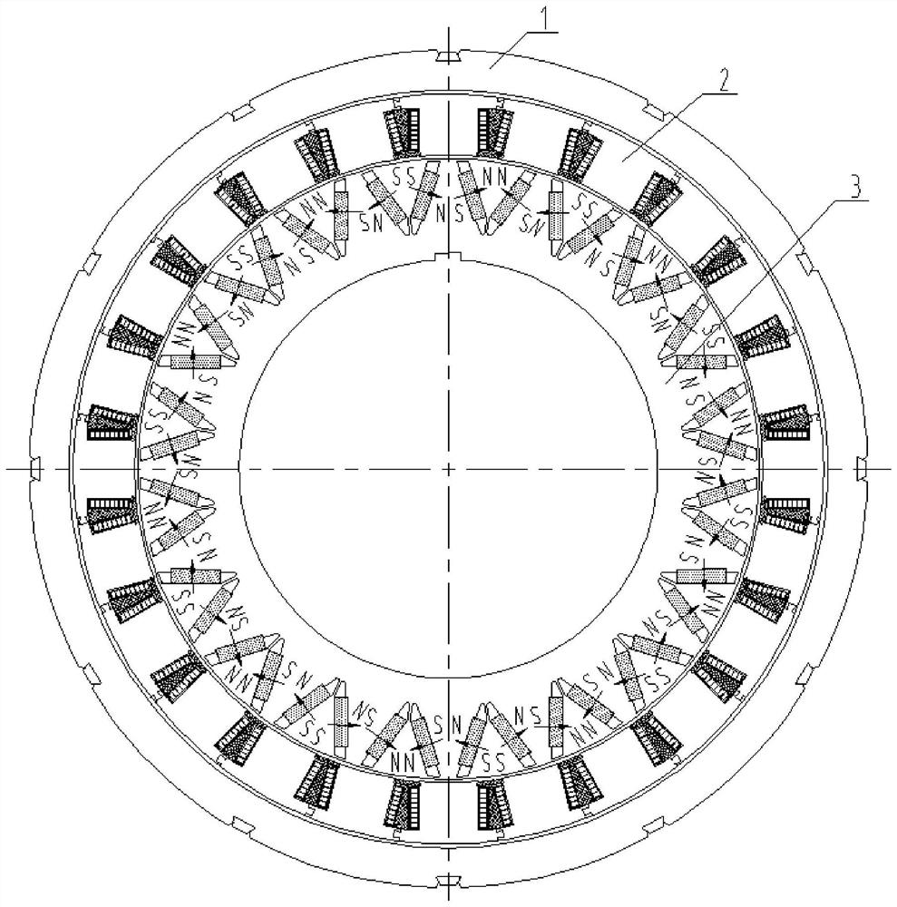
[0038] The magnetic circuit structure of the rotary yoke provided by this embodiment, such as figure 1 As shown, it includes a permanent magnet rotor and a winding rotor; the permanent magnet rotor includes: an inner permanent magnet rotor 3 and an outer rotor yoke 1; the outer rotor yoke 1 and the inner permanent magnet rotor 3 are rigidly connected, rotate synchronously, and have no speed Difference. The permanent magnetic flux starts from one magnetic pole, enters the nearest winding rotor tooth through the air gap, then bypasses the winding rotor winding through the outer rotor yoke, and returns to the original two adjacent magnetization through the adjacent tooth. Magnetic poles in different directions. The permanent magnet rotor rotates around the center, and the permanent magnet magnetic field remains unchanged or changes very little, so iron loss is not easy to occur, and the efficiency is improved.

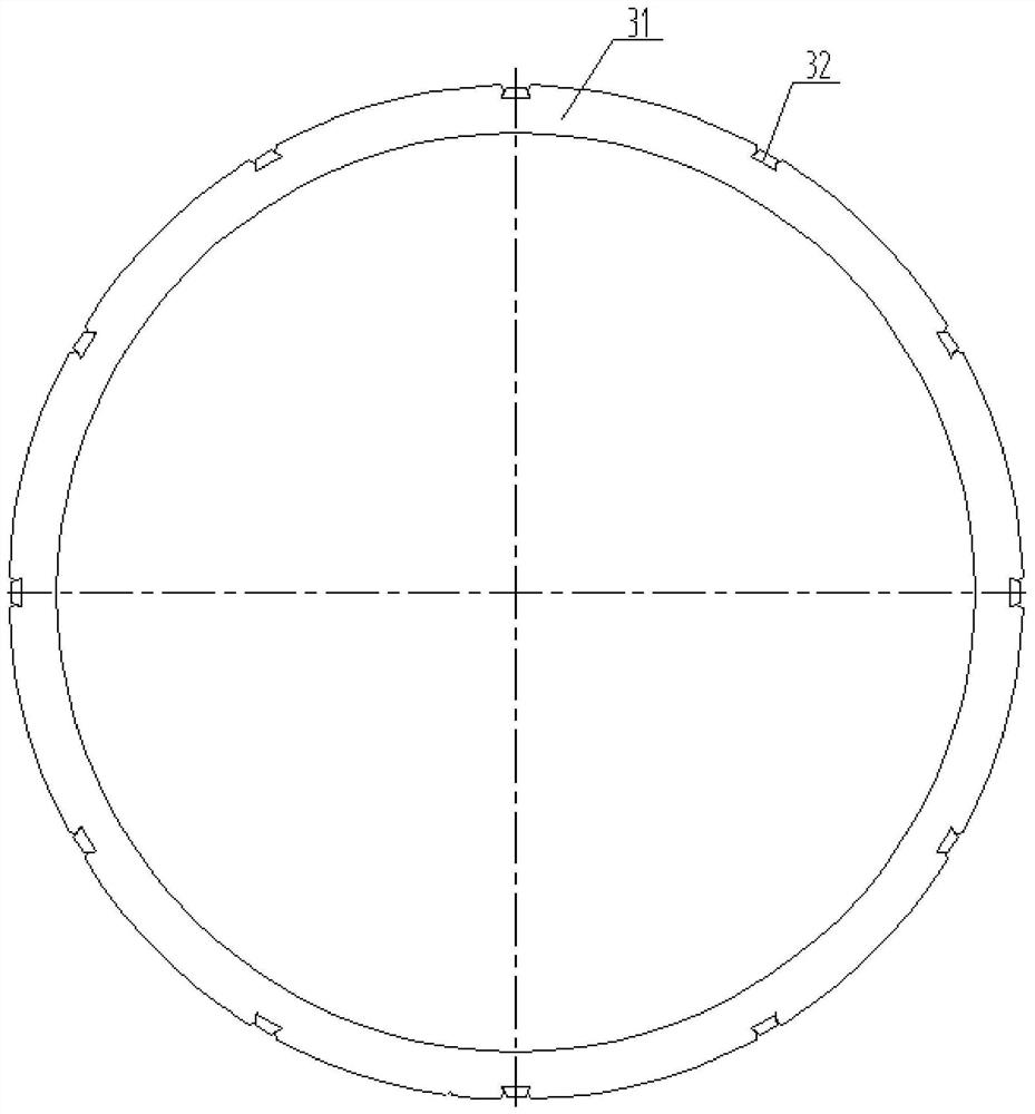
[0039] Such as figure 2 Shown is the outer rotor yoke structure....

Embodiment 2

[0046] The magnetic circuit structure of the rotating yoke provided by Embodiment 2, such as Figure 6 As shown, it includes a permanent magnet rotor and a winding rotor 2. The permanent magnet rotor includes an inner rotor yoke 4 and an outer permanent magnet rotor 5; the outer permanent magnet rotor 5 and the inner rotor yoke 4 are rigidly connected, rotate synchronously, and have no speed difference . The permanent magnetic flux starts from one magnetic pole, enters the nearest winding rotor tooth through the air gap, then bypasses the winding rotor winding through the outer rotor yoke, and returns to the original two adjacent magnetization through the adjacent tooth. Magnetic poles in different directions. The permanent magnet rotor rotates around the center, and the permanent magnet magnetic field remains unchanged or changes very little, so iron loss is not easy to occur, and the efficiency is improved.

[0047] The inner rotor yoke 4 is formed by laminating the inner ...


PUM


Abstract

The invention provides a rotary yoke magnetic circuit structure, and belongs to the technical field of permanent magnet magnetic circuits. The rotary yoke magnetic circuit structure comprises a permanent magnet rotor and a winding rotor, and is characterized in that the permanent magnet rotor comprises an inner permanent magnet rotor and an outer rotor yoke, and the inner permanent magnet rotor and the outer rotor yoke are rigidly connected and synchronously rotate without speed difference. According to the rotary yoke magnetic circuit structure provided by the invention, a winding rotor punching sheet adopts an oriented silicon steel sheet, and the rolling direction is radial, so that the magnetic density can be improved, the loss is reduced, and the comprehensive efficiency is improved.

Description

technical field [0001] The invention relates to the technical field of permanent magnetic circuits, in particular to a magnetic circuit structure of a rotating yoke. Background technique [0002] In the field of permanent magnetic circuit technology, a permanent magnetic circuit is generally composed of a magnetic potential source (permanent magnet), a magnetically conductive component, and an air gap. When there is a speed difference between the permanent magnet rotor and the winding rotor, an induced electromotive force is generated in the winding. When the winding is connected, an induced current loop is formed and an induced electromagnetic field is generated. The induced magnetic field interacts with the permanent magnetic field to transmit torque, which is controlled by the controller The size of the current of the winding rotor is used to control the size of its transmitted torque, so as to realize the function of speed regulation. [0003] The winding rotor includes...

Claims


Application Information

Patent Timeline
Patent Type & Authority Applications(China)
IPC IPC(8): H02K1/22H02K1/26H02K1/27H02K49/10
CPCH02K1/22H02K1/26H02K1/2753H02K49/102H02K49/106
Inventor 徐俊峰王宝家
Owner JIANGSU MAGNET VALLEY TECH
Why Eureka
Try Eureka