Spacer, manufacturing method thereof, image display apparatus using the spacer, and manufacturing method thereof

Inactive Publication Date: 2008-11-06
CANON KK
View PDF3 Cites 0 Cited by
  • Summary
  • Abstract
  • Description
  • Claims
  • Application Information

AI Technical Summary

Benefits of technology

[0008]One object of the present invention is to provide a spacer with small change of charging characteristics even when the image display apparatus has been driven for a long time, and the

Problems solved by technology

However, when a device in the vicinity of the spacer is activated, the spacer may be charged due to irradiation of a reflection electron to the spacer.
However, it has been found a phenomenon suc

Method used


Image

  • Spacer, manufacturing method thereof, image display apparatus using the spacer, and manufacturing method thereof
  • Spacer, manufacturing method thereof, image display apparatus using the spacer, and manufacturing method thereof
  • Spacer, manufacturing method thereof, image display apparatus using the spacer, and manufacturing method thereof

Examples


Example

EXAMPLE

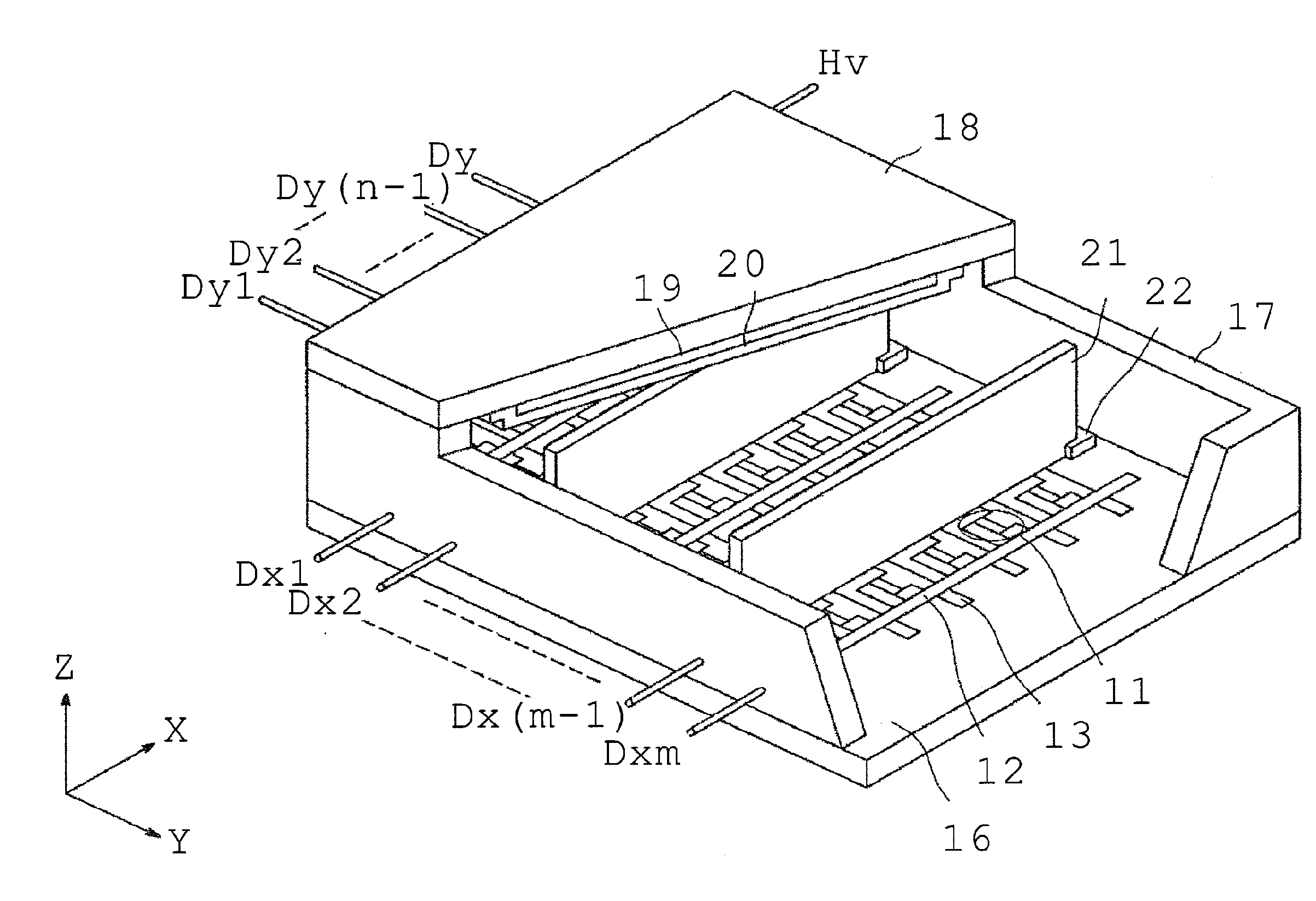
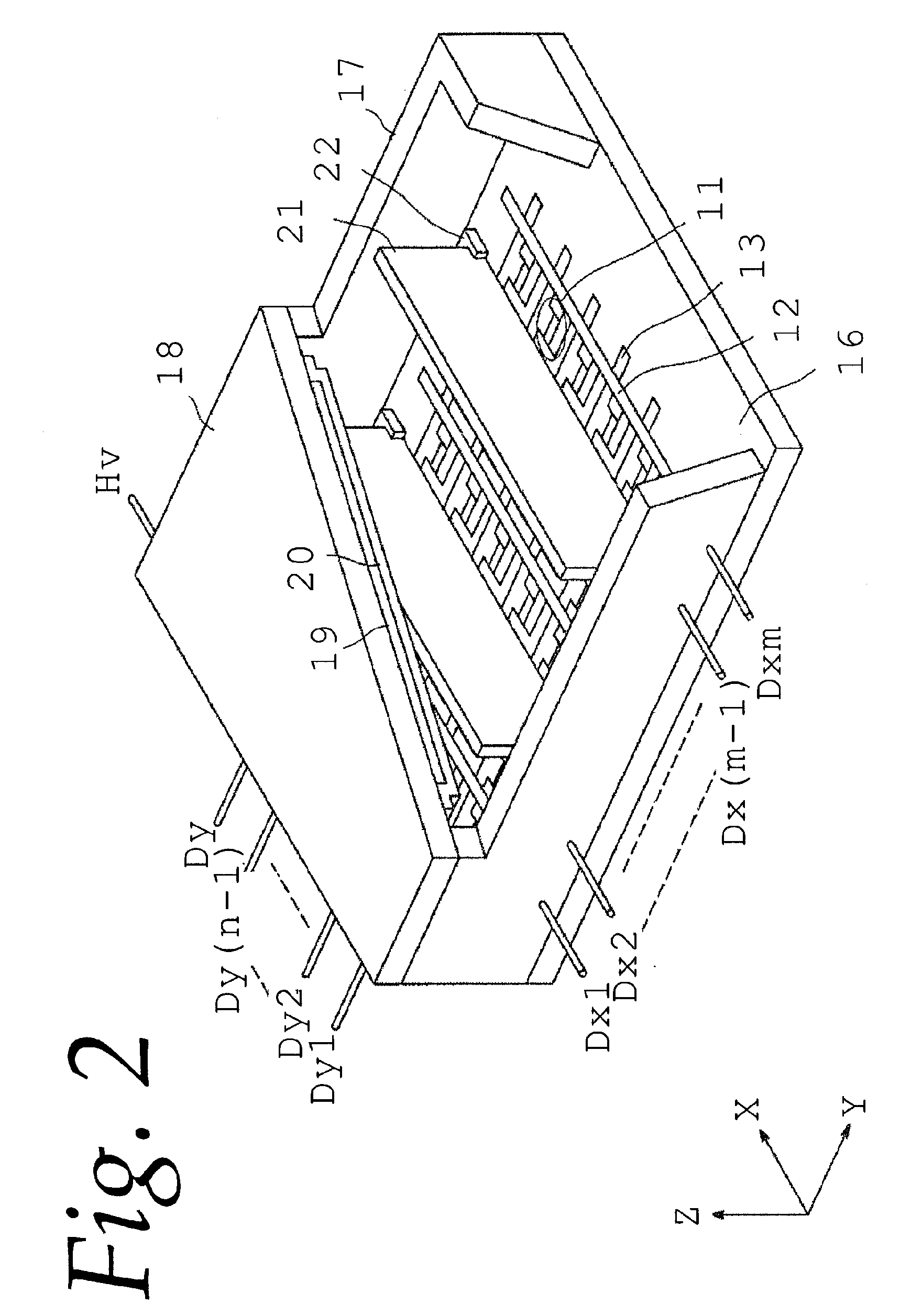
[0045]Next, a manufacturing method of a display panel of the image display apparatus to which the present invention is applied will be described with reference to FIG. 2 and FIG. 3 illustrating specific example.

(Step for Manufacturing Spacer)

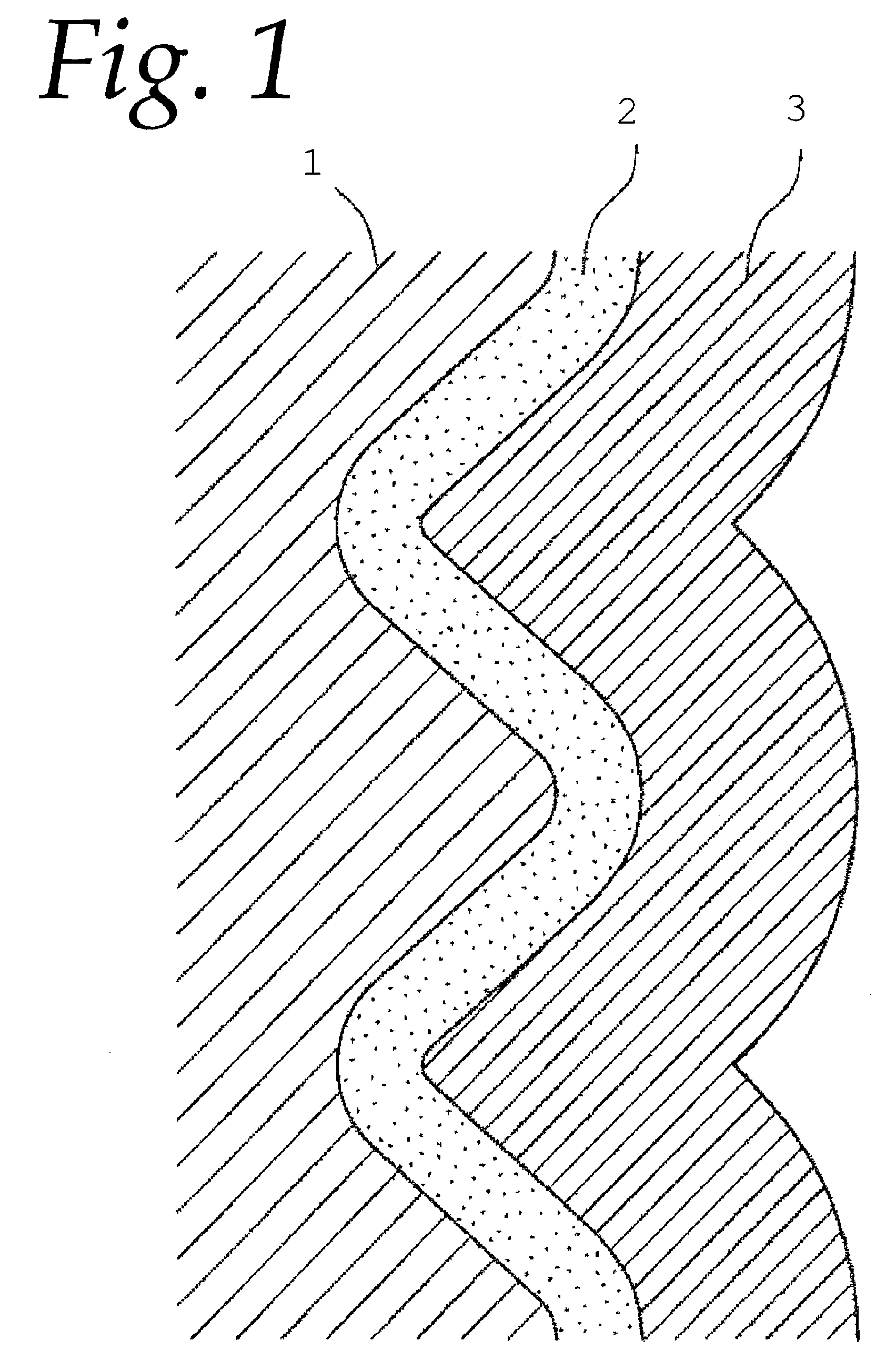
[0046]As a base material 1, a low-alkali glass for display, PD200, which is manufactured by Asahi Glass Co., Ltd. is used. Using this material, the base material 1 shown in FIG. 5 is manufactured by a heat drawing method. FIG. 5A is a plan view of the base material 1 and FIG. 5B is a sectional partial schematic view of the surface portion of the base material 1. According to the present example, the height of the spacer 21 is defined to be 2 mm and a length in a longitudinal direction is defined to be 900 mm.

[0047]According to the present example, concavity and convexity formed in a stripe along a longitudinal direction are provided on the surface of the base material 1. The shape of the concavity and convexity is a substantially sine wav...

Example

Comparative Example 1

[0085]As a comparative example 1, a spacer made of a single layer structure having one of the first film 2 and the second film 3 is manufactured under each film forming condition as same as in the embodiment, respectively. The image display apparatus is manufactured in same way as the embodiment, and the image evaluation measurement of the obtained image display apparatus is carried out in same way as the embodiment. The results are shown in the table 6.

TABLE 6ΔL on displayingΔL on displayinghigh gradationlow gradation(1 gradation)( 1 / 16 gradation)KindsFilmInitial ΔL(difference between(difference betweenSampleofForming(1 to 1 / 16before and afterbefore and afterNo.FilmCond.gradations)driving)driving)hFirst1≈0.020 LiFilm2≈0.020 Lj3≈0.011 LkSecond4≈0.020 LlFilm5≈0.020 Lm6≈0.020 Ln7≈0.020 Lo8≈0.020 L

[0086]In samples h, i, and j, comparing the beam spot barycentric positions on displaying a low gradation before and after longtime driving, shift about from 0.011 L to 0...

Example

Comparative Example 2

[0088]As a comparative example 2, a spacer having a layer structure in which the first film 2 and the second film 3 are layered in the reverse order compared with the embodiment, is manufactured under each film forming condition. That is, the first film 2 on the base material 1 is a film containing tungsten, germanium and nitrogen and the second film 3 on the first film 2 is a film having a structure that silver particles are dispersed in aluminum oxynitride. Each manufactured sample are shown in table 7.

TABLE 7Cond. for 2ND FilmCond. for1231ST Film(t = 80 nm)(t = 150 nm)(t = 300 nm)4 (t = 50 nm)—p—5 (t = 600 nm)—q—6 (t = 1200 nm)urv7 (t = 2000 nm)—s—8 (t = 2500 nm)—t—

[0089]The image display apparatus is manufactured in same way as the embodiment, and the image evaluation measurement of the obtained image display apparatus is carried out in same way as the embodiment. The results are shown in table 8.

TABLE 8ΔL on displayingΔL on displayinghigh gradationlow grada...


PUM


Abstract

There is provided a spacer for an image display apparatus having a base material and a film configuration in which a first film having a structure that silver particles are dispersed in aluminum oxynitride and a second film containing tungsten, germanium and nitrogen are layered on the base material in this order.

Description

BACKGROUND OF THE INVENTION[0001]1. Field of the Invention[0002]The present invention relates to a spacer used for a flat image display apparatus, a manufacturing method of this spacer, and an image display apparatus using this spacer, and a manufacturing method of the image display apparatus.[0003]2. Related Background Art[0004]As an image display apparatus that can achieve reduction in thickness and weight, a flat image display apparatus using a surface conduction electron emitting device has been suggested. The image display apparatus using such an electron emitting device forms a vacuum case by arranging a rear plate provided with an electron emitting device and a light emitting member for emitting a light due to irradiation of electrons so as to be opposed to each other and sealing them via a frame material on a periphery. In such an image display apparatus, in order to prevent deformation and damage of a base plate due to a difference of an atmospheric pressure between the ins...

Claims


Application Information

Patent Timeline
IPC IPC(8): H01J1/62H01J29/02H01J9/02
CPCH01J9/242H01J29/864H01J31/127Y10T428/25H01J2329/8635H01J2329/864H01J2329/8645H01J2329/863
Inventor KURODA, KAZUOSHIMIZU, YASUSHIOGURI, NORIAKI
Owner CANON KK
Why Eureka
Try Eureka