Spatial pose detection and adjustment method for engine case assembly

A technology of engine casing and adjustment method, applied in the direction of using optical devices, measuring devices, instruments, etc., can solve the problems of difficult to achieve automatic assembly, difficult to automate, damage to workpieces, etc., to improve the detection accuracy and the degree of assembly automation , Reduce the operation of workers, the effect of accurate display

Pending Publication Date: 2021-05-04
BEIJING POWER MACHINERY INST +1
View PDF6 Cites 2 Cited by
  • Summary
  • Abstract
  • Description
  • Claims
  • Application Information

AI Technical Summary

Problems solved by technology

Contact measurement mainly determines its attitude by contacting the receiver with a dial indicator, but it has the defects of damaging the workpiece and not easy to automate
Although non-contact measurement does not touch the workpiece, there is no mature method to fit the pose information of the product, so it is difficult to realize automated assembly

Method used


Image

  • Spatial pose detection and adjustment method for engine case assembly
  • Spatial pose detection and adjustment method for engine case assembly
  • Spatial pose detection and adjustment method for engine case assembly

Examples


Embodiment Construction

[0023] The present invention will be described in detail below with reference to the accompanying drawings and examples.

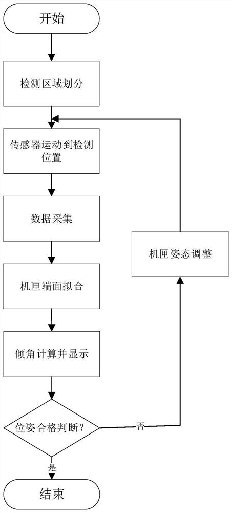
[0024] The present invention provides a method for detection and adjustment of the spatial position and attitude of the engine case assembly, combined with the actual production and assembly of an aero-engine, the specific process of realizing this solution is as follows figure 1 Shown:

[0025] Step 1. Data collection of sub-regions on the assembly surface

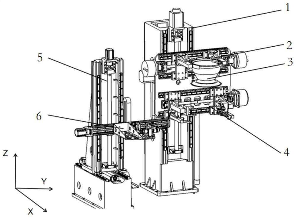
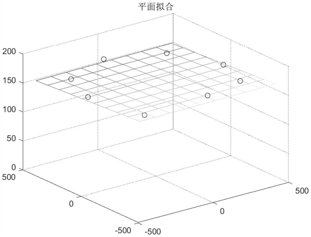
[0026] Fix the casing to be assembled on the assembly station, fix the laser sensor on the rotating turntable, and the optical path is vertically upward. Divide the casing assembly surface into 8 areas (according to the actual situation, the number of areas and the relative position relationship can be variable), move the laser sensor to the center point of the area, set n data collection positions, and record the laser display at this position respectively. number. During a data acquisition proces...


PUM


Abstract

The invention discloses a spatial pose detection and adjustment method for engine case assembly, and belongs to the technical field of manufacturing quality prediction and control. The method comprises the following steps of: 1, carrying out regional division on an assembly surface of an engine case, and then driving a laser sensor to carry out data acquisition by utilizing a detection adjusting device; 2, fitting pose information of the end face of the engine case according to the collected data; and 3, judging whether the pose of the case meets the assembly requirement or not, if so, ending the process, and if not, giving offset information, adjusting the pose of the engine case by the detection and adjustment device, and returning to the step 1 for re-detection and re-adjustment. An indirect measurement mode is adopted, the parallelism of the end face and the datum plane is judged by measuring the distance between the flange end face of the engine case and the datum plane, and the automation degree and the measurement efficiency of the detection link can be improved.

Description

technical field [0001] The invention relates to a method suitable for detecting and adjusting the assembly pose of an engine casing, belonging to the technical field of manufacturing quality prediction and control. Background technique [0002] With the rapid development of my country's military industry, the research and development progress of large-scale national defense products mainly including aero-engines, missiles and rockets is accelerating. Based on its working environment that requires high-speed flight, the airtightness of the product itself is very important. Therefore, extremely high requirements are placed on the assembly alignment accuracy of the product during the final assembly process. [0003] At present, most of the core machines are assembled manually. In order to realize automatic assembly, it is necessary to detect the pose of the parts during the assembly process and adjust them to meet the assembly position requirements. Common measurement methods...

Claims


Application Information

Patent Timeline
IPC IPC(8): G01B11/00G01B11/03
CPCG01B11/00G01B11/03
Inventor 周垚郑心豪金鑫张忠清张之敬郝娟
Owner BEIJING POWER MACHINERY INST
Why Eureka
Try Eureka