
Design method of multi-beam array based on UAV wireless energy transmission network

A technology of wireless energy transmission and design method, applied in radio transmission system, transmission system, network planning, etc., can solve the problem of limited flight time of drones, achieve high energy collection efficiency, and maximize the effect of energy collection by users

Active Publication Date: 2022-04-22
SOUTH CHINA UNIV OF TECH
View PDF11 Cites 0 Cited by
  • Summary
  • Abstract
  • Description
  • Claims
  • Application Information

AI Technical Summary

Problems solved by technology

However, limited by the capacity of the battery on the board, the flight time of the UAV is limited. Therefore, existing scholars study how to reduce the aerodynamic consumption and maximize the energy efficiency of the UAV to prolong the flight time of the UAV.

Method used


Image

  • Design method of multi-beam array based on UAV wireless energy transmission network
  • Design method of multi-beam array based on UAV wireless energy transmission network
  • Design method of multi-beam array based on UAV wireless energy transmission network

Examples


Embodiment

[0080] A multi-beam array design method based on UAV wireless energy transfer network, such as figure 1 shown, including the following steps:

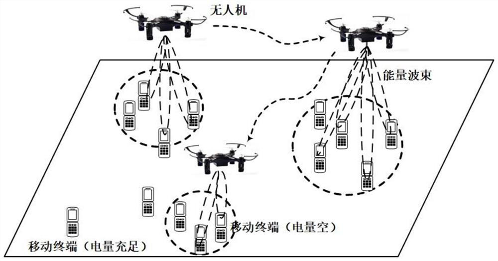
[0081] S1, such as figure 2 As shown, the downlink channel model of the wireless energy transfer network is established, and the channel model between the UAV and the user is formed by combining the energy beamforming with the line-of-sight link, as follows:

[0082] Assume that the downlink wireless power transfer (WPT) network system includes a quadrotor UAV and K users randomly distributed on land. The UAV is configured with a linear array of N antenna units, and the user is required to configure a single antenna. Suppose the location coordinate of user k is z k =(x k ,y k ), where k∈{1,…,K} is the index of the user set; the two-dimensional position of the drone is z u =(x u ,y u ), the flight height is h; the wireless channel between the UAV and user k is dominated by line-of-sight propagation, so the channel vector h k It...


PUM


Abstract

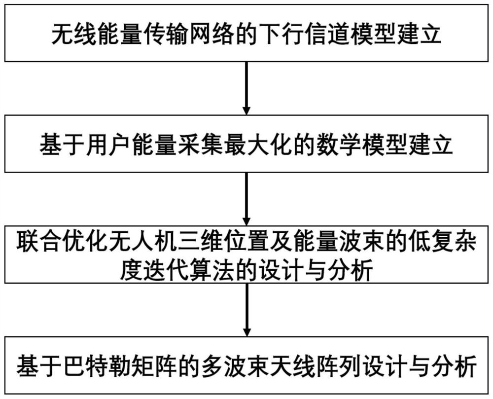
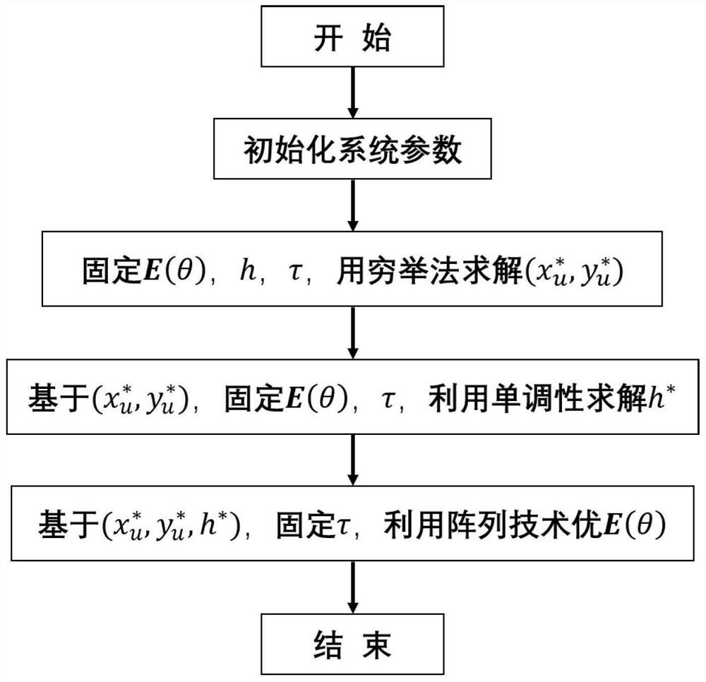
The invention discloses a multi-beam array design method based on an unmanned aerial vehicle wireless energy transmission network. The method includes the following steps: establishing a downlink channel model of a wireless energy transmission network; establishing a mathematical model based on user energy collection maximization; establishing a low-complexity iterative algorithm for joint optimization of three-dimensional position deployment and energy beams of unmanned aerial vehicles; matrix to design multi-beam array antennas. The present invention establishes the downlink channel model of the wireless energy transmission network and the mathematical model based on the maximization of user energy collection, and proposes a low-complexity algorithm for jointly optimizing the three-dimensional position deployment of the UAV, energy beams, and a multi-beam design scheme. While meeting the needs of internal users, it maximizes the energy harvested by users. Compared with single-beam WPT system and single-antenna WPT system, the proposed multi-beam WPT system has higher energy collection efficiency.

Description

technical field [0001] The invention relates to the technical field of wireless communication, in particular to a multi-beam array design method based on a wireless energy transmission network of an unmanned aerial vehicle. Background technique [0002] The history of microwave wireless power transfer can be traced back to the early work of Heinrich-Hertz in 1880. In the late 1960s, RF-based free-space wireless energy transfer was widely studied, two notable applications in microwave helicopters and solar-powered satellites. In these wireless energy transfer systems, high transmission power and large antenna aperture are utilized to overcome the propagation loss at high power reception. Over the past decade, there has been a resurgence of interest in wireless power transfer sources, primarily due to the growing need to provide low-cost and persistent energy supplies to wireless devices with relatively low power requirements, such as wireless sensors and personal networks. ...

Claims


Application Information

Patent Timeline
Patent Type & Authority Patents(China)
IPC IPC(8): H04W16/20H04W16/28H04W24/02H04B7/06H04B7/08
CPCH04W16/20H04W16/28H04B7/0617H04W24/02H04B7/086
Inventor 唐杰敖少鹏冯婉媚唐珩膑黄嘉毅
Owner SOUTH CHINA UNIV OF TECH
Learn More