Nonlinear Hydrostatic Control of a Wave Energy Converter

a wave energy converter and hydrostatic control technology, applied in special-purpose vessels, machines/engines, transportation and packaging, etc., can solve the problems of increasing the complexity of reactive power requirements, reducing the efficiency of wec operation, and increasing so as to maximize energy harvesting or extraction, increase the capture width, and increase the draft and speed of nonlinear buoys

Active Publication Date: 2020-11-12
MICHIGAN TECHNOLOGICAL UNIVERSITY +1
View PDF0 Cites 0 Cited by
  • Summary
  • Abstract
  • Description
  • Claims
  • Application Information

AI Technical Summary

Benefits of technology

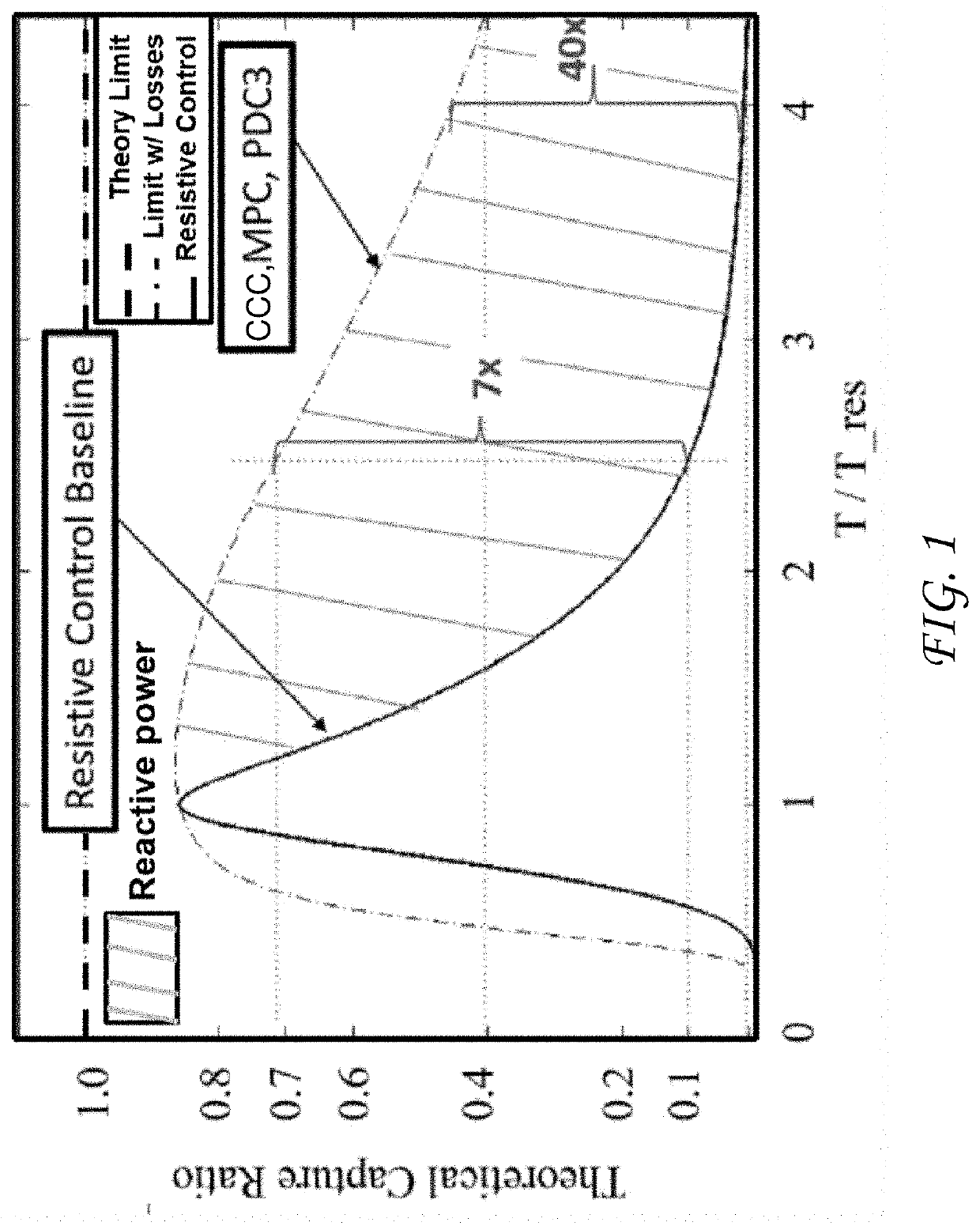
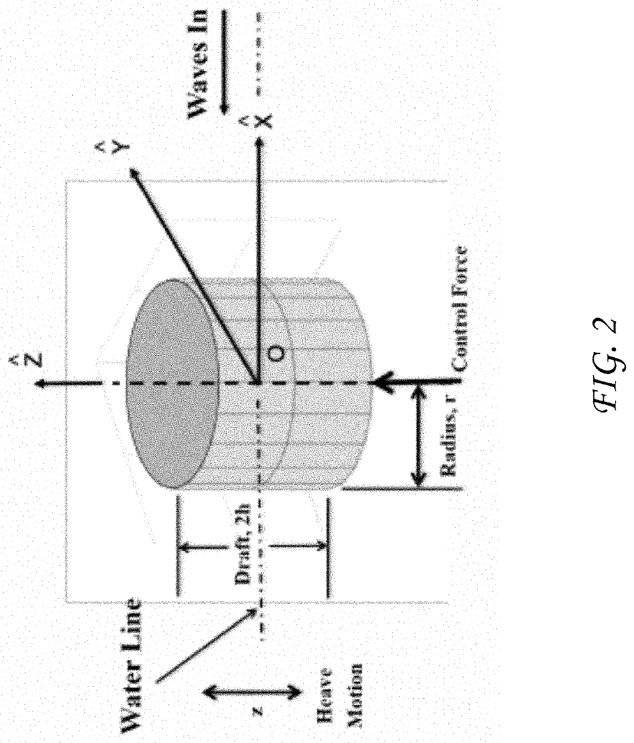
[0011]The nonlinear buoy geometry of the present invention produces energy storage and reactive power through nonlinear coupling between the buoy and wave interaction. The nonlinear buoy design shows desirable characteristics: 1) no required reactive power or energy storage due to the geometric buoy shape, 2) no cancellation of nonlinear terms that consume power, 3) the nonlinear resonator increases the capture width by including sub / super harmonics in the input waves, 4) by increasing the draft and speed of the nonlinear buoy more energy is harvested, and 5) the nonlinear buoy shape creates equivalent wave height and buoy motion measurements that are naturally incorporated.
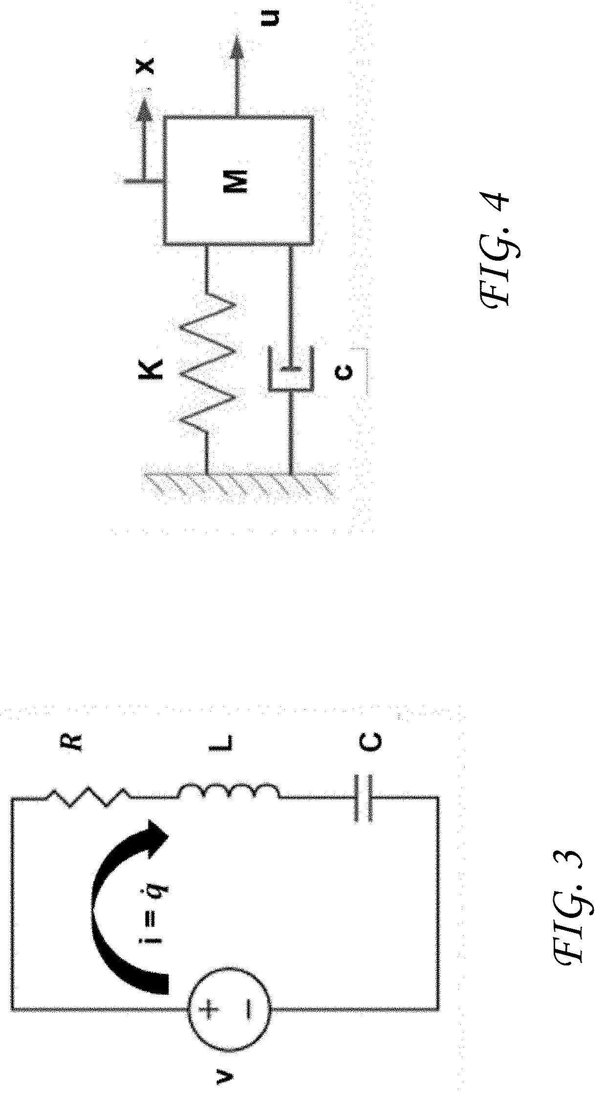
[0012]The invention further extends CCC of linear WECs to nonlinear (NL) WECs by designing optimal limit cycles with HSSPFC. The CCC for a regular wave is equivalent to a power factor of one in electrical power networks, equivalent to mechanical resonance in a mass-spring-damper (MSD) system, and equivalent to a linear limit cycle constrained to a Hamiltonian surface defined in HSSPFC. Specifically, the optimal linear limit cycle is defined as a second-order center in the phase-plane projection of the constant energy orbit across the Hamiltonian surface. This concept of CCC described by a linear limit cycle constrained to a Hamiltonian surface is extended to NL limit cycles constrained to a Hamiltonian surface to maximize energy harvesting or extraction from the wave motion by a NL WEC.

Problems solved by technology

However, when the WEC is off-resonance with the impacting waves the WEC operates much less efficiently.
However, both techniques require energy storage and power electronic elements and additional complexity to meet the reactive power requirements.

Method used


Image

  • Nonlinear Hydrostatic Control of a Wave Energy Converter
  • Nonlinear Hydrostatic Control of a Wave Energy Converter
  • Nonlinear Hydrostatic Control of a Wave Energy Converter

Examples


case study simulation results

[0078]Exemplary case studies and simulation results are described below for: i) nonlinear resonator, ii) single frequency inputs, and iii) multi-frequency spectrum inputs. A simplified optimal HG WEC design (optimize a subject to volumetric constraints leading to draft limits) is contrasted with a RCC WEC design. A volume constraint on displaced fluid is imposed on both the RCC and HG buoys to be equivalent:

VHG=VRCC.  (41)

[0079]The position constraint for the RCC and the HG WECs resulted in the draft limits shown in Table 2. The simplified optimization for the HG WEC, used for the Bretschneider spectrum, is a function of α which constrains the heave motion and the wave height. Note that α will be sea state dependent and can be adapted to meet each specific sea state condition for the actual application. For this example, the buoy effective mass was m=1.76×10⁵ kg, the linear damping coefficient was b=170 Ns / m, and linear stiffness coefficient was k=4.544915×10⁵ kg / s2. The nonlinear s...


PUM


Abstract

Increased energy harvesting is realized using a nonlinear buoy geometry for reactive power generation. By exploiting the nonlinear dynamic coupling between the buoy geometry and the potential wideband frequency spectrum of incoming waves in the controller/buoy design, increased power can be captured in comparison to conventional wave energy converter designs. In particular, the reactive power and energy storage system requirements are inherently embedded in the nonlinear buoy geometry, therefore requiring only simple rate-feedback control.

Description

CROSS-REFERENCE TO RELATED APPLICATIONS[0001]This application is a continuation-in-part of U.S. application Ser. No. 16 / 534,746, filed Aug. 7, 2019, which claims the benefit of U.S. Provisional Application No. 62 / 730,891, filed Sep. 13, 2018, both of which are incorporated herein by reference. This application also claims the benefit of U.S. Provisional Application No. 62 / 927,318, filed Oct. 29, 2019, and U.S. Provisional Application No. 62 / 927,590, filed Oct. 29, 2019, both of which are incorporated herein by reference.STATEMENT OF GOVERNMENT INTEREST[0002]This invention was made with Government support under Contract No. DE-NA0003525 awarded by the United States Department of Energy / National Nuclear Security Administration. The Government has certain rights in the invention.FIELD OF THE INVENTION[0003]The present invention relates to wave energy conversion and, in particular, to a shaped buoy that provides nonlinear hydrostatic control of a wave energy converter.BACKGROUND OF THE ...

Claims


Application Information

Patent Timeline
Patent Type & Authority Applications(United States)
IPC IPC(8): F03B13/18B63B22/00
CPCF03B13/1885B63B22/00B63B2035/4466B63B22/04Y02E10/30F05B2250/33F05B2250/20F05B2250/232
Inventor WILSON, DAVID G.BACELLI, GIORGIOCOE, RYAN GEOFFREYROBINETT, III, RUSH D.ABDELKHALIK, OSSAMA
Owner MICHIGAN TECHNOLOGICAL UNIVERSITY
Why Eureka
Try Eureka