Intelligent monitoring equipment for power grid equipment

A technology for intelligent monitoring and power grid equipment, which is applied in the direction of electrical equipment shells/cabinets/drawers, electrical components, casings/cabinets/drawer components, etc. Problems such as temperature rise at the end of the component

Active Publication Date: 2021-05-04
山西合邦电力科技有限公司
View PDF8 Cites 1 Cited by
  • Summary
  • Abstract
  • Description
  • Claims
  • Application Information

AI Technical Summary

Problems solved by technology

[0002] Power grid equipment generally refers to various equipment used to transmit and convert electric energy in the power grid. In the process of power transmission, it is generally in the form of high voltage or ultra-high voltage to reduce the loss of transmission. However, due to the complex internal structure of the transformer and the generally harsh working environment, various problems are often prone to stop the power transmission, and there are usually various abnormal data appearing before the problem occurs, and the transformer is monitored by intelligent monitoring equipment. Periodic data monitoring can be known and repaired before the transformer fails. However, in the proces

Method used


Image

  • Intelligent monitoring equipment for power grid equipment
  • Intelligent monitoring equipment for power grid equipment
  • Intelligent monitoring equipment for power grid equipment

Examples


Embodiment 1

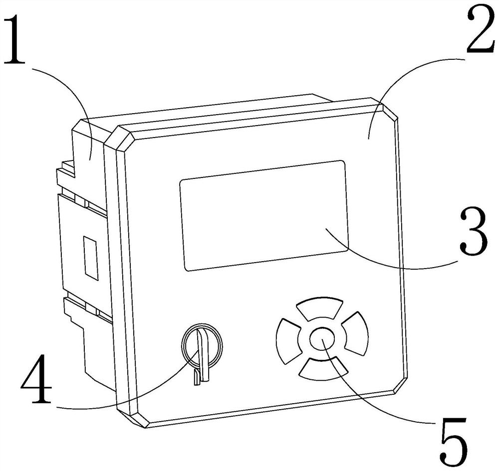
[0028] Such as Figure 1-Figure 5 As shown, the present invention provides an intelligent monitoring device for power grid equipment, its structure includes a monitoring device 1, a monitoring panel 2, a display 3, a knob 4, and a control button 5, and the rear end of the monitoring panel 2 is embedded and connected to the front end of the monitoring device 1 On the central surface, the rear end of the display 3 is embedded and connected to the inside above the front end of the monitoring panel 2, the rear end of the knob 4 is movably connected to the left side below the front end of the monitoring panel 2, and the rear end of the control button 5 is movably engaged with the monitoring panel 2. On the right side below the front of panel 2.

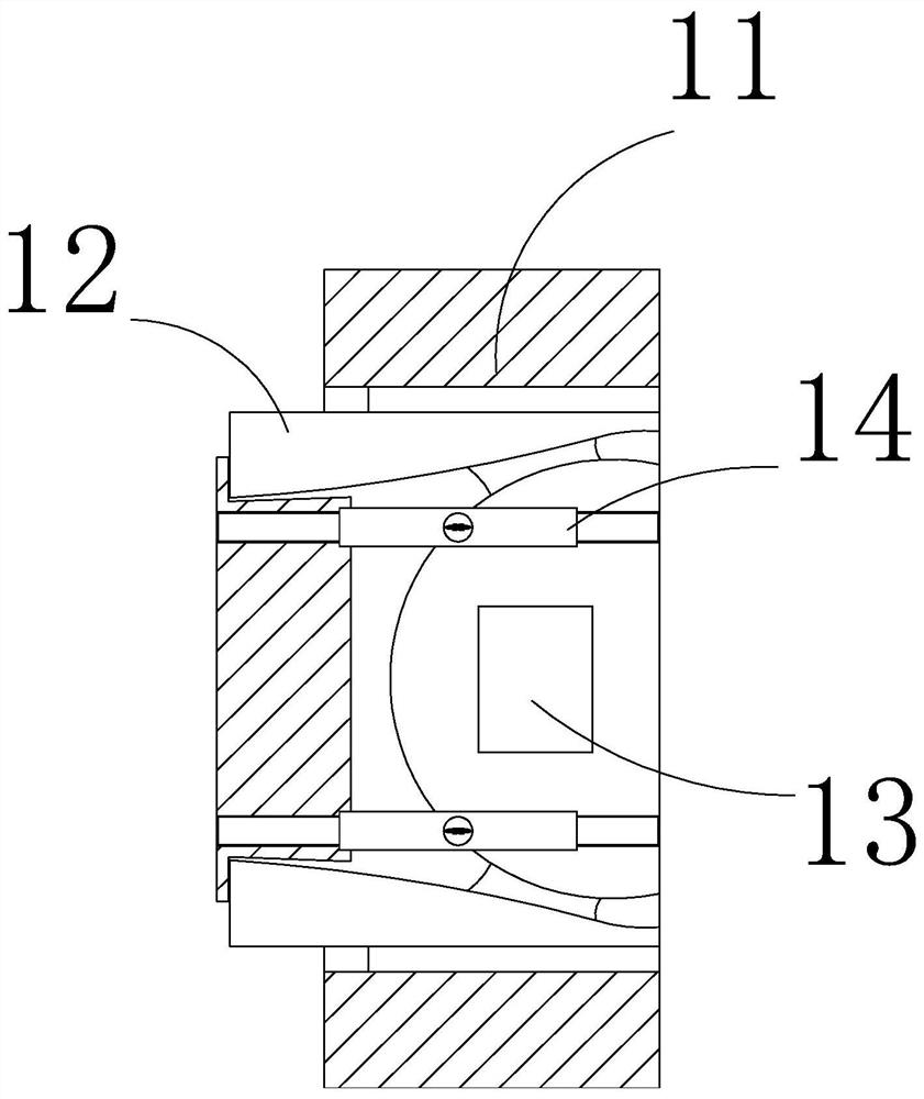
[0029] The monitoring device 1 includes a housing 11, an anti-collision block 12, a monitor 13, and an anti-covering device 14. The left side of the anti-collision block 12 is snapped and connected to the left side of the housing 11, and t...

Embodiment 2

[0036] Such as Figure 6-Figure 8 Shown:

[0037] Wherein, the crushing device a22 includes a connection seat b1, a fixed block b2, a crushing mechanism b3, and a protective strip b4, the lower end of the fixed block b2 is embedded and connected to the upper end of the connection seat b1, and the crushing mechanism b3 is movably connected to the fixed block b2 Inside on the left side, the protective strip b4 is fitted and connected to the left surface of the fixed block b2. The protective strip b4 is a strip structure with smooth sides, which allows the broken plastic bag to be better connected with the crushing mechanism b3 Make contact, not easily blocked by friction and unable to travel.

[0038] Wherein, the crushing mechanism b3 includes an engaging shaft b31, a bump b32, a connecting ring b33, a crushing knife b34, and a crushing block b35. Embedded and connected to the inner wall of the bump b32, the right end of the crushing knife b34 is fitted and connected to the o...


PUM


Abstract

The invention discloses an intelligent monitoring equipment for power grid equipment. The intelligent monitoring equipment structurally comprises a monitoring device, a monitoring panel, a displayer, a rotary knob and a control button, the rear end of the monitoring panel is fixedly connected to the center surface of the front end of the monitoring device in an embedded mode, and the rear end of the displayer is connected to the interior of the upper portion of the front end of the monitoring panel in an embedded mode; the rear end of the rotary knob is movably connected to the left side of the lower portion of the front end of the monitoring panel, and the rear end of the control button is movably clamped to the right side of the lower portion of the front end of the monitoring panel. According to the intelligent monitoring equipment, a force-bearing block is squeezed when a plastic bag sleeves the surface of the device so that a connecting block of a shearing device pulls a connecting rod to open the shearing mechanism, and the plastic bag is pierced once; due to the fact that the pressure is reduced, the shearing mechanism shrinks, then a shearing knife at the side end of a crushing device shears the plastic bag under the elastic force action of a torsional spring, and a blade embedded in the front end of the shearing knife generates high pressure on the plastic bag in the shearing process through an extremely-thin-sheet-shaped body structure of the blade, so that the plastic bag is more easily sheared to be broken; the monitoring device is prevented from being sealed by the plastic bag and generating abnormal high temperature inside.

Description

technical field [0001] The invention relates to the field, in particular to an intelligent monitoring device for power grid equipment. Background technique [0002] Power grid equipment generally refers to various equipment used to transmit and convert electric energy in the power grid. In the process of power transmission, it is generally in the form of high voltage or ultra-high voltage to reduce the loss of transmission. However, due to the complex internal structure of the transformer and the generally harsh working environment, various problems are often prone to stop the power transmission, and there are usually various abnormal data appearing before the problem occurs, and the transformer is monitored by intelligent monitoring equipment. Periodic data monitoring can be known and repaired before the transformer fails. However, in the process of monitoring the substation in the community, the intelligent monitoring equipment of the power grid equipment in the prior art ...

Claims


Application Information

Patent Timeline
IPC IPC(8): H05K5/02
CPCH05K5/0217
Inventor 甘艳云
Owner 山西合邦电力科技有限公司
Why Eureka
Try Eureka