Automatic external cardiac compression device

A heart and automatic technology, applied in the direction of cardiac stimulation, artificial respiration, respirator, etc., can solve the problems of improving the survival rate of comatose personnel, and achieve the effect of improving the survival rate of personnel, increasing the survival rate, and simple structure

Inactive Publication Date: 2021-05-07
曲士和
View PDF1 Cites 1 Cited by
  • Summary
  • Abstract
  • Description
  • Claims
  • Application Information

AI Technical Summary

Problems solved by technology

However, it is not possible to automatically perform chest compressions on patients during rescue and simulate artificial respiration to further improve the chances of survival of comatose people.

Method used


Image

  • Automatic external cardiac compression device
  • Automatic external cardiac compression device
  • Automatic external cardiac compression device

Examples


specific Embodiment approach 1

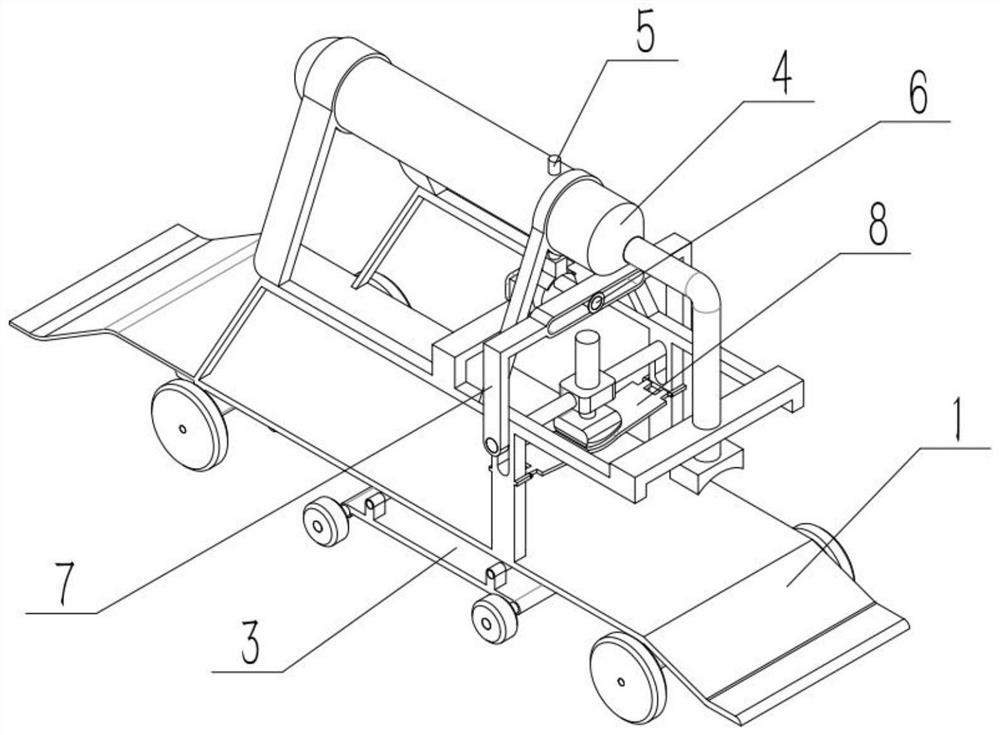
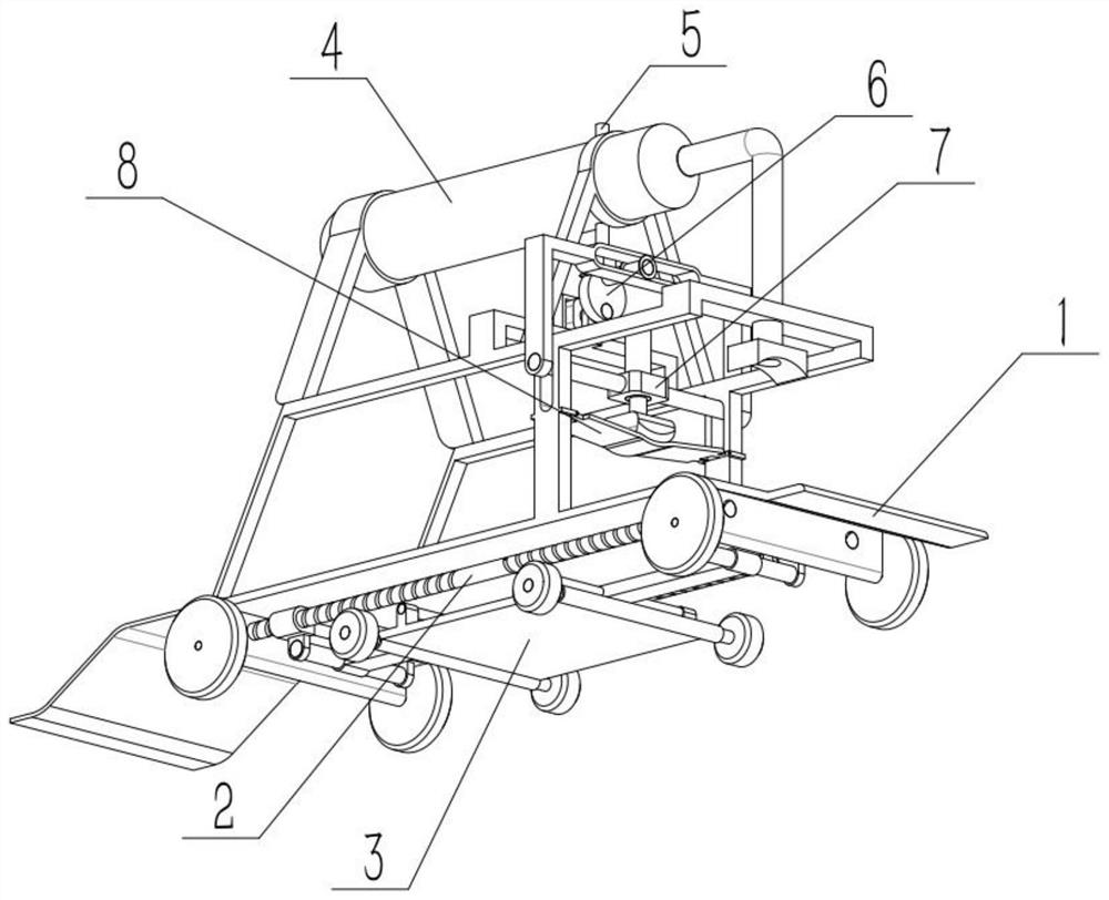
[0033] Such as Figure 1-11 As shown, an automatic chest compression device includes a moving mechanism 1, a power mechanism 2, a folding mechanism 3, a tank body mechanism 4, a pressure mechanism 5, a rotating mechanism 6, a pressing mechanism 7 and a buffer mechanism 8, and is characterized in that: The power mechanism 2 is connected to the lower end of the moving mechanism 1, the folding mechanism 3 is connected to the power mechanism 2, the tank body mechanism 4 is connected to the middle part of the upper end of the moving mechanism 1, the pressure mechanism 5 is connected in the tank body mechanism 4, and the pressure mechanism 5 The lower end is in contact with the rotating mechanism 6 , the pressing mechanism 7 is connected to the middle part of the moving mechanism 1 , the buffer mechanism 8 is affixed to the middle part of the moving mechanism 1 , and the lower end of the pressing mechanism 7 is in contact with the buffer mechanism 8 .

[0034] The present invention ...

specific Embodiment approach 2

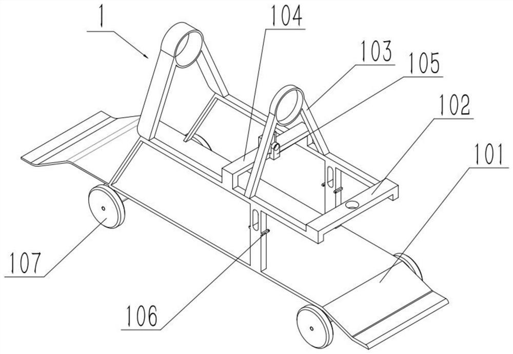
[0036] Such as Figure 1-11 As shown, an automatic chest compression device, the moving mechanism 1 includes a moving plate 101, an upper frame 102, a top ring 103, a concave plate 104, a concave plate convex seat 105, a lower convex seat 106 and a fixed convex plate 108, the upper frame 102 is affixed to the upper end of the moving plate 101, the left end of the upper end of the upper frame 102 and the middle part of the upper end are respectively affixed with a top ring 103, the concave plate 104 is fixed in the middle part of the upper end of the upper frame 102, and the convex seat 105 of the concave plate is affixed to the concave plate 104 In the middle part of the right end, there are four lower convex seats 106, and two lower convex seats 106 are affixed to the front and rear ends of the upper frame 102 middle part respectively, and a fixed convex plate 108 is respectively affixed to the left and right ends of the movable plate 101 lower end. When an emergency occurs, ...

specific Embodiment approach 3

[0038] Such as Figure 1-11 As shown, an automatic chest compression device, the power mechanism 2 includes a motor I 201, a lead screw 202, a belt 203, an engagement frame 204 and a limit frame 205, two lead screws 202 are provided, and one lead screw 202 The left and right ends are respectively rotatably connected to the rear ends of the two fixed convex plates 108, and the left and right ends of the other lead screw 202 are respectively rotatably connected to the front ends of the two fixed convex plates 108. The output shaft of the motor I 201 is connected to the The lead screw 202 at the rear end is fixedly connected, the motor I 201 is fixedly connected to the fixed convex plate 108 at the left end, the two lead screws 202 are connected through the transmission of the belt 203, two engaging frames 204 are provided, and the front and rear ends of one engaging frame 204 are respectively The left ends of the two lead screws 202 are threaded, and the front and rear ends of t...


PUM


Abstract

The invention relates to a compression device, and particularly relates to an automatic external cardiac compression device. The automatic external cardiac compression device comprises a moving mechanism, a power mechanism, a folding mechanism, a tank mechanism, a pressure mechanism, a rotating mechanism, a compression mechanism and a buffer mechanism, wherein the power mechanism is connected to the lower end of the moving mechanism, the folding mechanism is connected to the power mechanism, the tank mechanism is connected to the middle of the upper end of the moving mechanism, the pressure mechanism is connected in the tank mechanism, the lower end of the pressure mechanism is in contact with the rotating mechanism, the compression mechanism is connected to the middle of the moving mechanism, the buffer mechanism is fixedly connected to the middle of the moving mechanism, and the lower end of the compression mechanism is in contact with the buffer mechanism. The automatic external cardiac compression device can automatically perform external cardiac compression on a patient during rescue and meanwhile simulate artificial respiration to further improve the survival probability of coma persons.

Description

technical field [0001] The invention relates to a compression device, more specifically to an automatic chest compression device. Background technique [0002] For example, Publication No. CN201921179335.9 A Cardiac Compression Device for Emergency Use in Cardiology Department This utility model discloses a heart compression device for emergency use in Cardiology Department, which relates to the technical field of medical devices. The heart compression device for first aid in the cardiology department includes a backboard, an installation seat, a pole, a beam, a telescopic mechanism, a lifting mechanism and a pressing block. The mounting base is fixedly installed on the back plate, one end of the vertical pole extends into the mounting base, the other end is fixedly connected with the beam, and is vertically arranged with the beam, the driving motor is fixedly installed in the beam, and is connected with the screw rod, and the screw rod is sleeved It is located outside the ...

Claims


Application Information

Patent Timeline
Patent Type & Authority Applications(China)
IPC IPC(8): A61H31/00A61M16/00
CPCA61H31/006A61M16/00
Inventor 曲士和
Owner 曲士和
Why Eureka
Try Eureka