
Heat insulation structure of gas turbine waste heat conveying pipeline

A technology for delivery pipes and gas turbines, which is applied to combustion engines, engine cooling, internal combustion piston engines, etc. It can solve problems such as inconvenience, waste heat damage of delivery pipes, inability to dissipate and absorb waste heat, and achieve the effect of preventing and avoiding heat.

Pending Publication Date: 2021-05-07
浙江大亚节能科技有限公司
View PDF4 Cites 0 Cited by
  • Summary
  • Abstract
  • Description
  • Claims
  • Application Information

AI Technical Summary

Problems solved by technology

After the industrial revolution, with the development and use of mechanical equipment, as a source of energy used by mechanical equipment, gas turbines have become popular all over the world, and gas turbines need the combustion and heating of fuel to convert heat energy. , the unnecessary heat will follow. As for this, in the waste heat treatment process, the heat insulation structure of the conveying pipe is very important, and the heat insulation structure of the current waste heat conveying pipe generally adopts thickened pipe wall to reduce the heat loss. Little waste heat has an impact on the outside of the conveying pipe. Such a structure will not only cause damage to the conveying pipe due to waste heat, but also cannot dissipate and absorb waste heat well, which is very inconvenient

Method used


Image

  • Heat insulation structure of gas turbine waste heat conveying pipeline
  • Heat insulation structure of gas turbine waste heat conveying pipeline
  • Heat insulation structure of gas turbine waste heat conveying pipeline

Examples


Embodiment Construction

[0023] The invention will be further described below in conjunction with the accompanying drawings and specific embodiments.

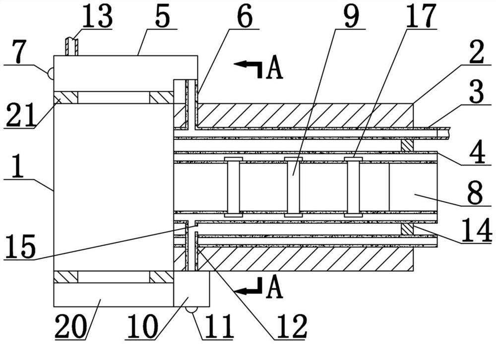
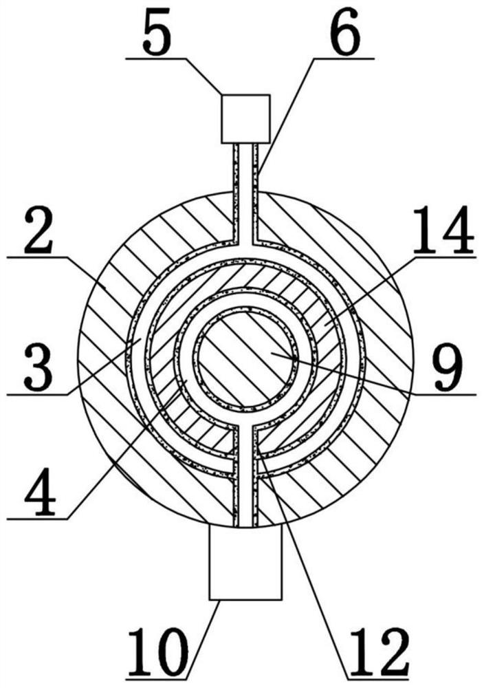
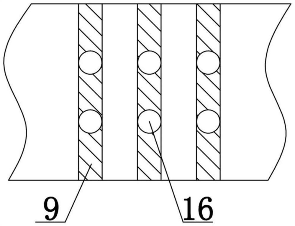
[0024] Such as figure 1 , figure 2 In the example shown, a thermal insulation structure of a gas turbine waste heat transmission pipeline includes a gas turbine 1 and a transmission pipe 2, the gas turbine 1 is connected to the transmission pipe 2, and a drain pipe 3 is installed on the transmission pipe 2, and heat conduction power generation Machine 8 and screen cloth one 9, the outer wall of drainage pipe 3 is connected with the inner side wall of conveying pipe 2, and screen cloth one 9 comprises several, and several screen cloth one 9 are evenly distributed in conveying pipe 2, and screen cloth one 9 and The heat conduction generators 8 are all connected to the inner side wall of the drain pipe 3, the material of the screen 9 is a heat conduction material, the heat conduction generator 8 is connected to the screen 9, and the gas turbine 1 is pro...


PUM


Abstract

The invention discloses a heat insulation structure of a gas turbine waste heat conveying pipeline. The heat insulation structure of the gas turbine waste heat conveying pipeline uses waste heat to carry out heat insulation. The structure comprises a gas turbine and a conveying pipe, wherein the gas turbine is connected with the conveying pipe, a drainage pipe, a heat conduction generator and first screens are installed on the conveying pipe, the outer side wall of the drainage pipe is connected with the inner side wall of the conveying pipe, the multiple first screens are evenly distributed in the conveying pipe, the first screens and the heat conduction generator are both connected with the inner side wall of the drainage pipe, the first screens are made of a heat conduction material, the heat conduction generator is connected with the first screens, and a water pump is arranged on the gas turbine, electrically connected with the heat conduction generator and communicated with the drainage pipe. The structure has the beneficial effects that the purpose of using waste heat to carry out heat insulation can be achieved through the drainage pipe, the heat conduction generator and the water pump; through an exhaust fan and an exhaust pipe, the effect of preventing the drainage pipe from being heated is achieved; and the supporting effect of the exhaust pipe is achieved through the first screens.

Description

technical field [0001] The invention relates to the technical field of gas turbine accessories, in particular to a heat insulation structure for a gas turbine waste heat delivery pipeline. Background technique [0002] A gas turbine is a heat engine that uses fuel combustion to heat a circulating working medium to convert thermal energy into mechanical energy. After the industrial revolution, with the development and use of mechanical equipment, as a source of energy used by mechanical equipment, gas turbines have become popular all over the world, and gas turbines need the combustion and heating of fuel to convert heat energy. , the unnecessary heat will follow. As for this, in the waste heat treatment process, the heat insulation structure of the conveying pipe is very important, and the heat insulation structure of the current waste heat conveying pipe generally adopts thickened pipe wall to reduce the heat loss. Little waste heat has an impact on the outside of the conv...

Claims


Application Information

Patent Timeline
Patent Type & Authority Applications(China)
IPC IPC(8): F01N5/02F01N13/08F01N13/14F01P11/00
CPCF01N5/02F01N13/08F01N13/14F01P11/00Y02T10/12
Inventor 蓝骏
Owner 浙江大亚节能科技有限公司
Features
  • Generate Ideas
  • Intellectual Property
  • Life Sciences
  • Materials
  • Tech Scout
  • Unparalleled Data Quality
  • Higher Quality Content
  • 60% Fewer Hallucinations
Learn More