
Injection joints, injection tubes, burners and gas stoves
A technology for injection tubes and gas stoves, which is applied in the field of cookers, and can solve problems such as gas impact, inability to fix injection tubes, and structural limitations.
- Summary
- Abstract
- Description
- Claims
- Application Information
AI Technical Summary
Problems solved by technology
Method used
Image

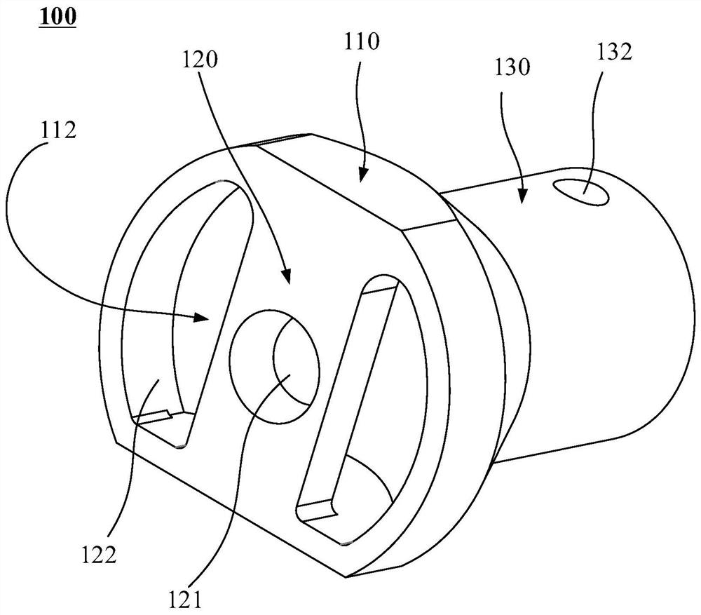
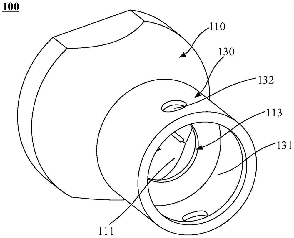
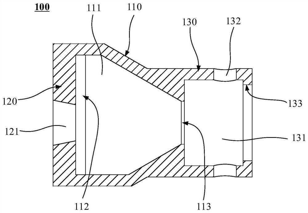
Examples
Embodiment Construction
[0079] In the following, the present invention will be more clearly and completely described by means of an embodiment in conjunction with the accompanying drawings, but the present invention is not limited to the scope of the embodiment.
[0080] like Figure 1-3 As shown, an injection joint 100 of this embodiment is used to connect with the gas mixing section of the injection pipe and can be offset relative to the gas mixing section. The injection joint 100 includes an injection section 110, The ejection section 110 has an ejection channel 111 inside, and the two ends of the ejection channel 111 are respectively provided with an ejection port 112 and a gas outlet port 113 along the gas flow direction. The ejection section 110 also has a limiting portion 120, which is arranged at one end of the injection port 112, and the limiting portion 120 is provided with a limiting through hole 121, which is used for inserting and limiting the through hole 121 compatible gas nozzles.
...
PUM
 Abstract
Description
Claims
Application Information