
Locking movement mechanism of actuator

A technology of motion mechanism and actuator, applied in the field of locking motion mechanism, which can solve the problems of potential safety hazards, small torsional holding force of the driving device, lack of self-locking function, etc.

Pending Publication Date: 2021-05-11
NINGBO HUADE AUTOMOBILE PARTS
View PDF1 Cites 2 Cited by
  • Summary
  • Abstract
  • Description
  • Claims
  • Application Information

AI Technical Summary

Problems solved by technology

However, there are certain disadvantages in the existing structure of this type of actuator. For example, the patent application number is: CN201720028717.6, which discloses a compact actuator, which lacks the self-locking function, so the torsion holding force of the driving device is relatively low. Small, behind the small door of the closed fuel filler cap or the small door of the charging port cover, it can still be opened manually by force, which poses a great potential safety hazard

Method used


Image

  • Locking movement mechanism of actuator
  • Locking movement mechanism of actuator
  • Locking movement mechanism of actuator

Examples


Embodiment Construction

[0035] The present invention will be described in further detail below in conjunction with the accompanying drawings and specific embodiments.

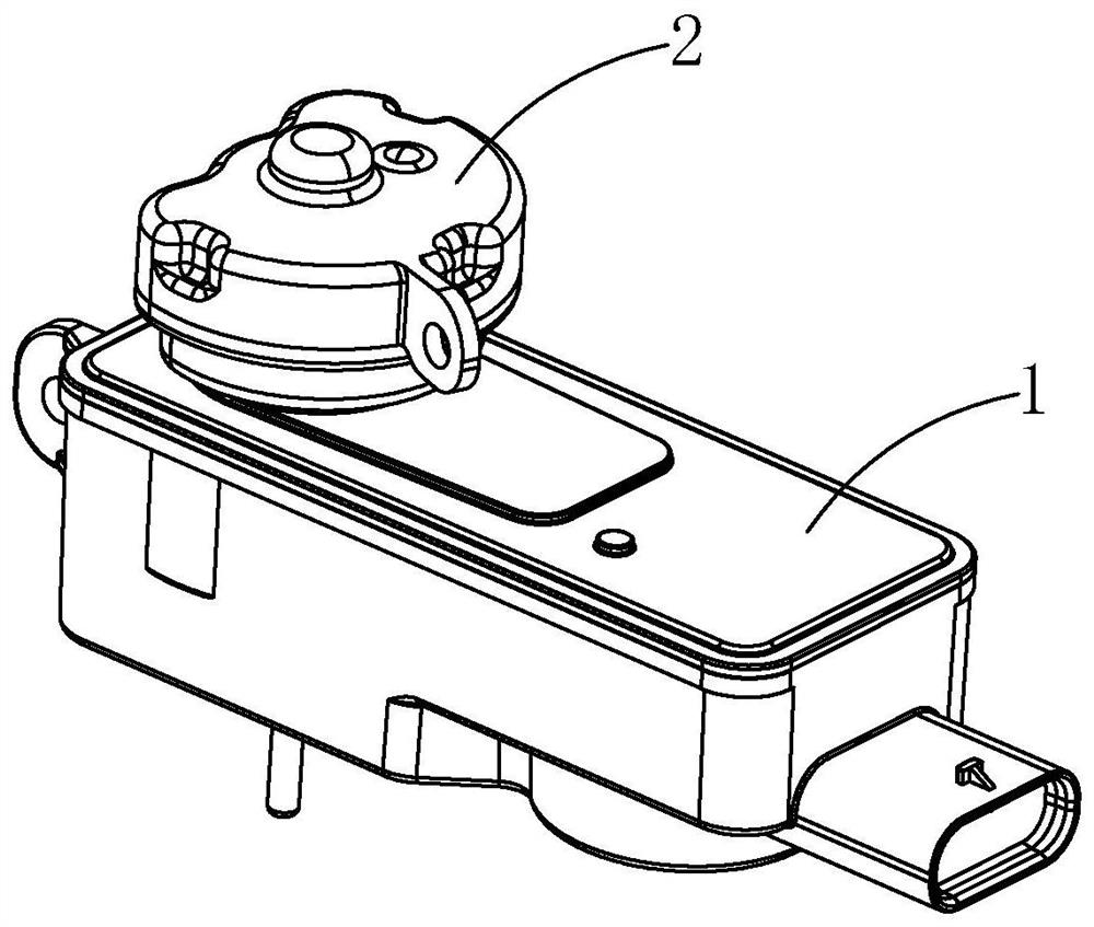
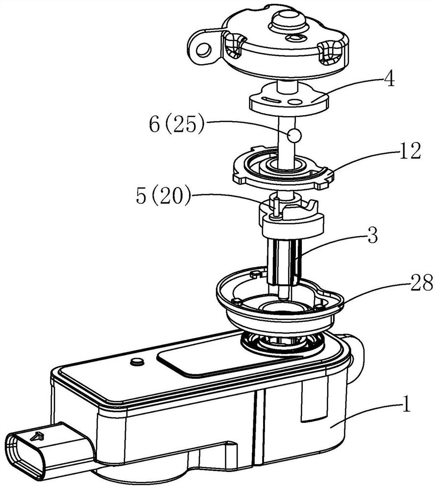
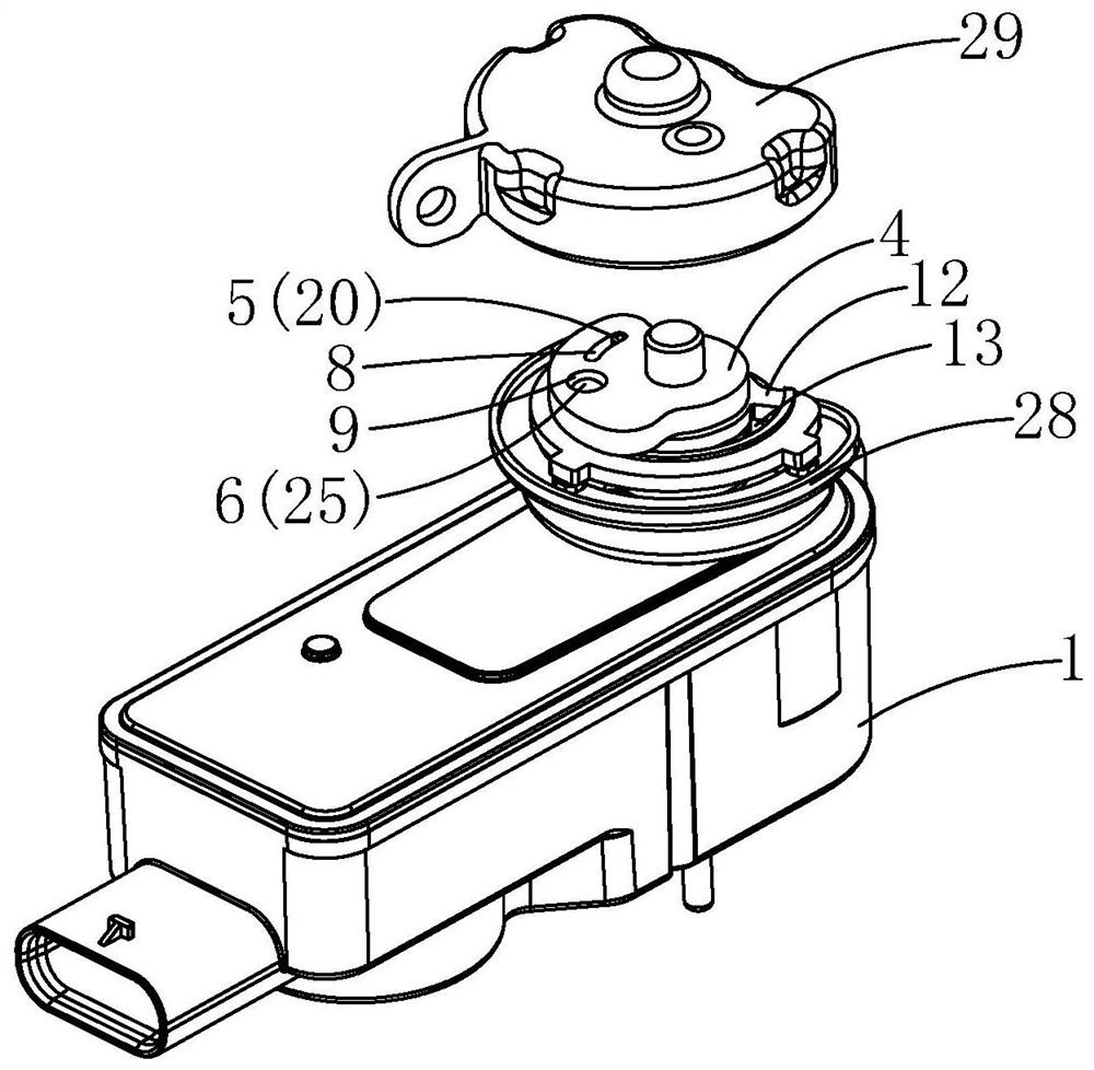
[0036] refer to Figure 1 to Figure 14 , a locking motion mechanism of an actuator, including an actuator body 1 and a one-way output device, the one-way output device includes a fixed housing 2, a driving shaft 3, a driven output shaft 4, and a 3 and the first driving member 5 and the second driving member 6 between the driven output shaft 4;

[0037] Wherein, the driving shaft 3 is in transmission connection with the actuator body 1, the driving shaft 3 is provided with a through hole 7, and the driven output shaft 4 is at least partly pierced through the through hole 7 middle;

[0038] The driven output shaft 4 is provided with a first interlocking groove 8 and a second interlocking groove 9, the first driving member 5 is fixedly connected to the driving shaft 3, and the first driving member 5 Inserted into the first linkage gro...


PUM


Abstract

A locking movement mechanism of an actuator comprises an actuator body and a one-way output device, wherein the one-way output device comprises a fixed shell, a driving shaft, a driven output shaft, a first driving piece and a second driving piece, and the first driving piece and the second driving piece are arranged between the driving shaft and the driven output shaft; a first linkage groove and a second linkage groove are formed in the driven output shaft, the first driving piece is fixedly connected with the driving shaft, the first driving piece is inserted into the first linkage groove, and at least part of the second driving piece is located in the second linkage groove and is in clearance fit with the second linkage groove; a driving groove is formed in the driving shaft, a locking groove is formed in the fixed shell, the second driving piece is movably arranged in the driving groove, and the second driving piece can be clamped into or separated from the locking groove under the guide of the driving groove. According to the invention, the power transmission from the driving shaft to the driven output shaft is guaranteed, and power transmission from the driven output shaft to the driving shaft is also cut off, so that the driving shaft can be effectively prevented from being driven by external force, and therefore using safety is guaranteed.

Description

technical field [0001] The invention relates to the technical field of driving devices, in particular to a locking motion mechanism applied to an actuator of a vehicle. Background technique [0002] Nowadays, with the development of the automobile industry and the increase in the popularity of automobiles, people have higher and higher requirements for the performance of automobiles, and they also pay more attention to the speed, convenience and safety of various operations of vehicles. Therefore, automobile companies It is especially important for the improvement of vehicle structure and the application of new technologies. [0003] In a complete vehicle, there are tens of thousands of parts, which are equipped with various actuators to realize intelligent control of the electric opening or closing of various parts. [0004] For example, in the small fuel door of the vehicle, in the traditional structure, the small door of the fuel filler cap or the small door of the charg...

Claims


Application Information

Patent Timeline
IPC IPC(8): B60K15/05B62D25/24
CPCB60K15/05B62D25/24B60K2015/0561
Inventor 周利怀杨幸辉
Owner NINGBO HUADE AUTOMOBILE PARTS
Learn More