
Integration device for travelling crane moving track

A docking device and track connection technology, which is applied to the joints of rails, rails, roads, etc., can solve the problems of troublesome and time-consuming, high failure rate, and the inability of the transport trolley to drive into the fixed track, etc., to achieve novel structure, precise docking, and track docking fast and precise results

Pending Publication Date: 2021-05-14
HUANGSHI HUATIAN AUTOMATION EQUIP
View PDF0 Cites 0 Cited by
  • Summary
  • Abstract
  • Description
  • Claims
  • Application Information

AI Technical Summary

Problems solved by technology

[0002] The driving track of the existing train is installed on the joist of the driving track, the movable rail support is directly installed on the driving, the movable track is installed on the movable rail support, and the fixed rail support is installed on the fixed rail auxiliary beam, and the fixed rail is installed On the support of the fixed rail, in such a structure, since the joist of the driving track and the auxiliary beam of the fixed rail are relatively independent and separated from each other, when the vehicle is loaded, the joist of the driving track will bend downward, and at this time , the movable rail support installed on the train and the movable rail installed on the movable rail support also sink, resulting in relative displacement of the movable rail lower than the fixed rail. After the relative displacement of the movable rail and the fixed rail, It will cause the transport trolley installed on the movable track to fail to drive into the fixed track, or cause the transport trolley installed on the fixed track to fail to drive into the movable track. Therefore, this method has a high failure rate and troublesome and time-consuming troubleshooting.

Method used


Image

  • Integration device for travelling crane moving track

Examples


Embodiment Construction

[0007] Embodiments of the invention will be described in further detail below in conjunction with the accompanying drawings.

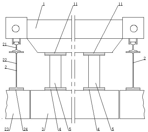
[0008] see figure 1 , the present invention includes a trolley 1, which is characterized in that it also includes two rail connection assemblies 2 symmetrically arranged left and right, a movable rail 3, a plurality of movable rail supports 4 and a plurality of movable rail connectors 5, on the trolley 1 Several connecting plates 11 are provided, and each of the track connecting assemblies 2 includes a driving track 21, a driving track joist 22, a fixed track 23 and a fixed rail support 24, and the driving track 21 is mounted on the driving track joist 22. At the upper end, the fixed rail support 24 is mounted on the lower end of the joist 22 of the driving track, the fixed rail 23 is mounted on the fixed rail support 24, and the driving 1 is mounted on the driving rail 21 of the two rail connection assemblies 2 , the upper part of each of the movable...


PUM


Abstract

The invention discloses an integration device for a travelling crane moving track which comprises a travelling crane and is characterized by further comprising two rail connecting assemblies arranged in a bilateral symmetry mode, a movable track, a plurality of movable rail supporting pieces and a plurality of movable track connecting pieces. Multiple connecting plates are arranged on the travelling crane. Each track connecting assembly comprises a crane track, a crane track supporting beam, a fixed track and a fixed track supporting piece, the crane track is installed at the upper end of the crane track supporting beam, the fixed track supporting piece is installed at the lower end of the crane track supporting beam, and a fixed track is installed on the fixed track supporting piece; the traveling crane is installed on the traveling crane tracks of the two rail connecting assemblies, the upper portion of each movable track connecting piece is connected with the connecting plate, the lower portion of each movable track connecting piece is connected with the corresponding movable track supporting pieces, and the movable tracks are installed on the movable tracks supporting pieces. The invention is novel in structure, rapid and accurate in track integration, safe and reliable.

Description

technical field [0001] The invention relates to conveying equipment, in particular to a docking device for traveling rails. Background technique [0002] The driving track of the existing train is installed on the joist of the driving track, the movable rail support is directly installed on the driving, the movable track is installed on the movable rail support, and the fixed rail support is installed on the fixed rail auxiliary beam, and the fixed rail is installed On the support of the fixed rail, in such a structure, since the joist of the driving track and the auxiliary beam of the fixed rail are relatively independent and separated from each other, when the vehicle is loaded, the joist of the driving track will bend downward, and at this time , the movable rail support installed on the train and the movable rail installed on the movable rail support also sink, resulting in relative displacement of the movable rail lower than the fixed rail. After the relative displaceme...

Claims


Application Information

Patent Timeline
Patent Type & Authority Applications(China)
IPC IPC(8): E01B11/42B65G35/00
CPCE01B11/42B65G35/00
Inventor 陈朝阳喻小雷曹锋汤华炬张镱曦
Owner HUANGSHI HUATIAN AUTOMATION EQUIP
Learn More