Stamping type wood composite board punching device

A punching device and stamping technology, which is applied in wood stamping and other directions, can solve the problems of hole position deviation and failure to meet the use requirements

Active Publication Date: 2021-05-18
山东久乐福木业有限公司
View PDF9 Cites 3 Cited by
  • Summary
  • Abstract
  • Description
  • Claims
  • Application Information

AI Technical Summary

Problems solved by technology

[0004] In order to overcome the disadvantage that the manual hand-held drilling machine is easy to make the position of the hole shift, so as not to meet the needs of use, the technical problem is to provide a stamping type wood-composite board drilling device that does not require manual drilling.

Method used


Image

  • Stamping type wood composite board punching device
  • Stamping type wood composite board punching device
  • Stamping type wood composite board punching device

Examples


Embodiment 1

[0064] A punching type wood composite board punching device, such as figure 1 As shown, it includes a bottom plate 1 , a supporting mechanism 2 and a punching mechanism 3 . The top of the bottom plate 1 is provided with a supporting mechanism 2 , and the supporting mechanism 2 is provided with a punching mechanism 3 .

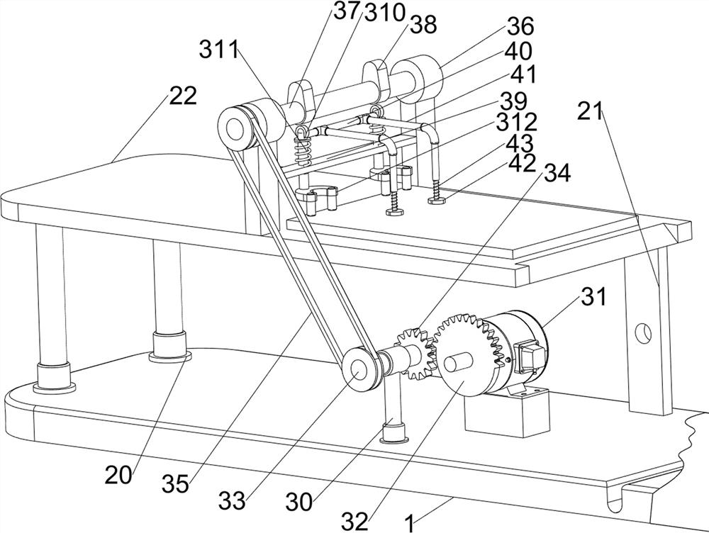
[0065] like figure 2 As shown, the support mechanism 2 includes a support column 20, a mounting plate 21 and a workbench 22, the top left side of the bottom plate 1 is provided with a support column 20 symmetrically front and rear, the top right side of the bottom plate 1 is provided with a mounting plate 21 symmetrically front and rear, and the top of the mounting plate 21 is provided A workbench 22 is connected with the top of the support column 20 .

[0066] like figure 2As shown, the punching mechanism 3 includes a first bearing seat 30, a motor 31, a first missing gear 32, a first rotating shaft 33, a first gear 34, a pulley set 35, a second bearing se...

Embodiment 2

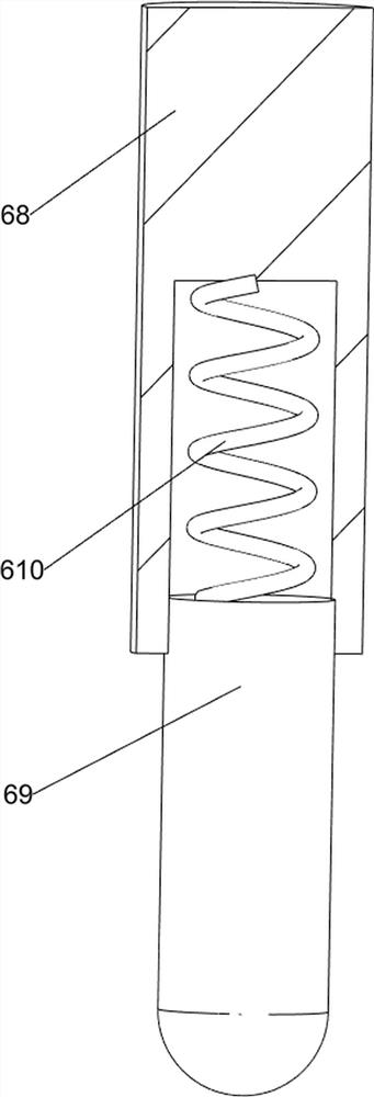
[0069] On the basis of Example 1, as figure 2 As shown, it also includes a fixing mechanism 4, the fixing mechanism 4 includes a second connecting rod 40, a pressing rod 41, a pressing head 42 and a second spring member 43, and a second connecting rod is connected between the upper side of the first connecting rod 310 40. There are pressure rods 41 on both the front and rear sides of the second connecting rod 40, and a pressure head 42 is slidably provided in the pressure rod 41, and a second spring member 43 is connected between the pressure rod 41 and the pressure head 42.

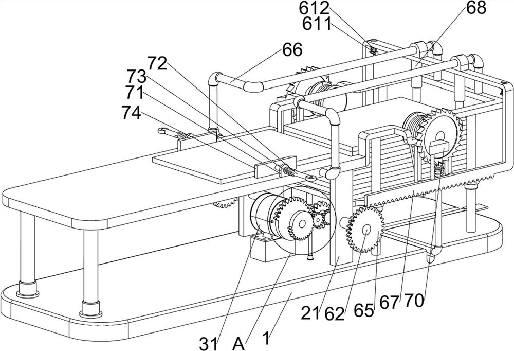
[0070] like image 3 As shown, it also includes a feeding mechanism 5. The feeding mechanism 5 includes a fixed column 50, a feeding plate 51, a mounting frame 52, a rope pulley 53, a pulling rope 54, a ratchet wheel 55, a first installation rod 56, a first card The teeth 57, the third spring member 58 and the pedal 59, four fixing columns 50 are evenly arranged on the right side of the top of the bott...


PUM


Abstract

The invention relates to a punching device, in particular to a stamping type wood composite board punching device. According to the stamping type wood composite board punching device, manual drilling work is not needed. The stamping type wood composite board punching device comprises a bottom plate and a punching mechanism, and a supporting mechanism is arranged at the top of the bottom plate; and the punching mechanism is arranged on the supporting mechanism. Through the arrangement of the supporting mechanism and the punching mechanism, under the cooperation of workers, punching work can be continuously conducted on a composite board; a fixing mechanism is arranged to clamp the composite board during punching work, so that punching work is more convenient; and through cooperation of a feeding mechanism and a pushing mechanism, automatic feeding work of the composite board can be completed, and manpower is further saved.

Description

technical field [0001] The invention relates to a punching device, in particular to a punching type wood composite board punching device. Background technique [0002] Nowadays, in the decoration work, in order to save wood loss, wood composite panels are usually used. In order to facilitate the placement of some small pendants, such as bedside lamps and decorative objects, it is necessary to drill the wood composite panels for direct placement. Bedside lamps and decorations, or the next step of processing work, are currently drilled manually with a drilling machine, but manual drilling with a drilling machine can easily offset the position of the hole, so that the to usage requirements. [0003] Therefore, it is necessary to design a punching device for punching wood composite panels without manual drilling. SUMMARY OF THE INVENTION [0004] In order to overcome the disadvantage that the position of the hole is easily displaced by the manual hand-held drilling machine, ...

Claims


Application Information

Patent Timeline
Patent Type & Authority Applications(China)
IPC IPC(8): B27M1/04
CPCB27M1/04Y02P70/10
Inventor 不公告发明人
Owner 山东久乐福木业有限公司
Why Eureka
Try Eureka