
Multi-rotor unmanned aerial vehicle and control method thereof

A multi-rotor unmanned aerial vehicle and rotor technology, applied in the field of unmanned aerial vehicles, can solve the problems of unbalanced lift of the multi-rotor unmanned aerial vehicle, the crash of the multi-rotor unmanned aerial vehicle, and the inability to maintain a stable flight.

Active Publication Date: 2021-05-18
BEIJING JINGDONG QIANSHITECHNOLOGY CO LTD
View PDF14 Cites 0 Cited by
  • Summary
  • Abstract
  • Description
  • Claims
  • Application Information

AI Technical Summary

Problems solved by technology

[0003] In the process of implementing the disclosed concept, the inventor found that there are at least the following problems in the related art: the electronic speed controller and motor on one or more arms Or the rotor fails, which eventually leads to the unbalanced lift of the multi-rotor UAV and the inability to maintain a stable flight, which is prone to problems such as crashes of the multi-rotor UAV

Method used


Image

  • Multi-rotor unmanned aerial vehicle and control method thereof
  • Multi-rotor unmanned aerial vehicle and control method thereof
  • Multi-rotor unmanned aerial vehicle and control method thereof

Examples


Embodiment Construction

[0072] Hereinafter, embodiments of the present disclosure will be described with reference to the drawings. It should be understood, however, that these descriptions are exemplary only, and are not intended to limit the scope of the present disclosure. In the following detailed description, for purposes of explanation, numerous specific details are set forth in order to provide a thorough understanding of the embodiments of the present disclosure. It may be evident, however, that one or more embodiments may be practiced without these specific details. Also, in the following description, descriptions of well-known structures and techniques are omitted to avoid unnecessarily obscuring the concept of the present disclosure.

[0073] The terminology used herein is for the purpose of describing particular embodiments only, and is not intended to be limiting of the present disclosure. The terms "comprising", "comprising", etc. used herein indicate the presence of stated features, ...


PUM


Abstract

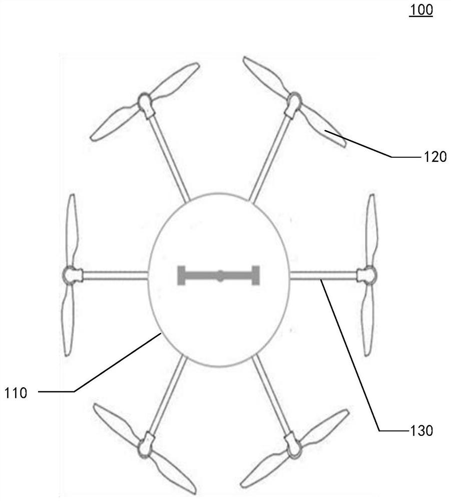
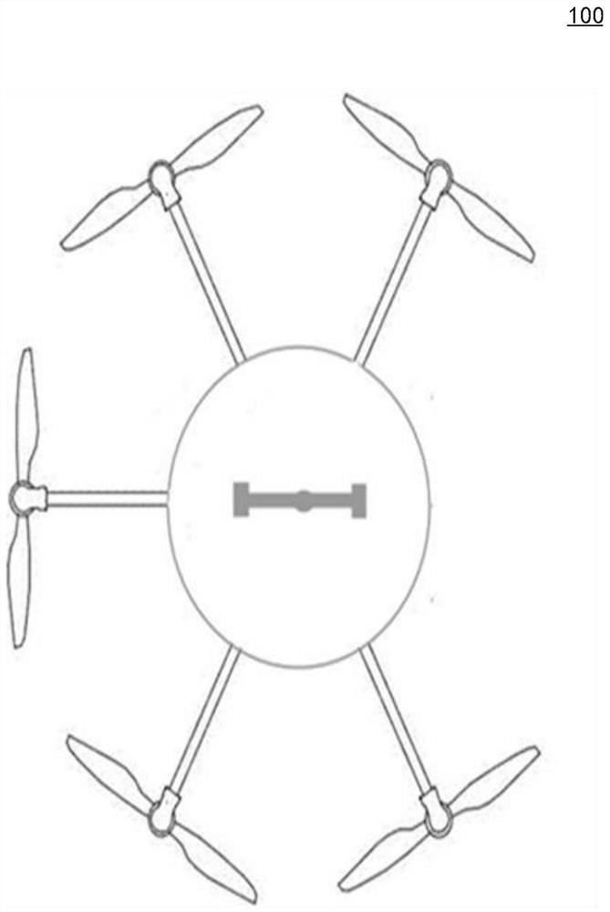
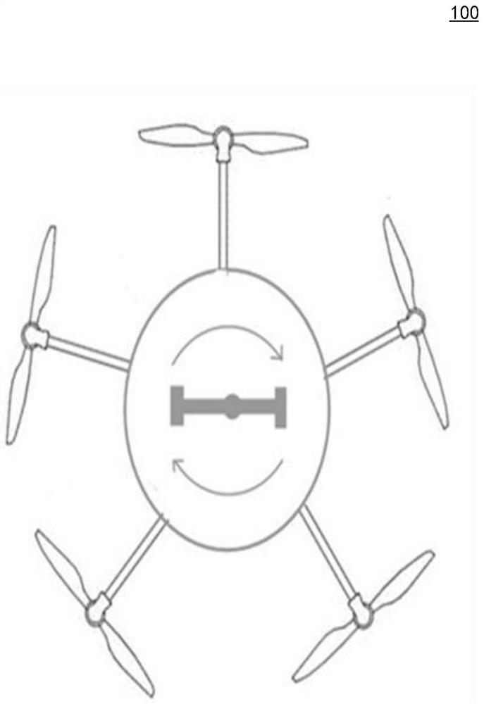
The invention provides a multi-rotor unmanned aerial vehicle. The multi-rotor unmanned aerial vehicle comprises a fuselage; multiple arms, wherein each arm comprises a first arm part and a second arm part, the first arm part is connected with the fuselage, a rotor wing is arranged on the second arm part, and the first arm part and the second arm part are detachably connected through an arm disconnecting device; and a power balancing device which is arranged between the fuselage and the first vehicle arm part and used for maintaining power balance of the multi-rotor unmanned aerial vehicle when the vehicle arm disconnecting device disconnects the second vehicle arm part from the first vehicle arm part. The invention further provides a multi-rotor unmanned aerial vehicle control method.

Description

technical field [0001] The present disclosure relates to the technical field of unmanned aerial vehicles, and more specifically, relates to a multi-rotor unmanned aerial vehicle and a control method thereof. Background technique [0002] Unmanned aircraft, referred to as "drone", is an aircraft operated by radio remote control equipment. The multi-rotor UAV is one of them. The motor on each arm rotates to drive the rotor to generate thrust. The multi-rotor UAV controls the trajectory of the aircraft through the mutual cooperation between the rotors. [0003] In the process of realizing the concept of the present disclosure, the inventor found that there are at least the following problems in the related art: the electronic governor, motor or rotor on one or more arms fails, which eventually leads to the unbalanced lift of the multi-rotor UAV However, it cannot maintain a stable flight, and it is prone to problems such as multi-rotor UAV crashes. Contents of the invention...

Claims


Application Information

Patent Timeline
IPC IPC(8): B64C27/08B64C27/82
CPCB64C27/08B64C27/82
Inventor 郄新越
Owner BEIJING JINGDONG QIANSHITECHNOLOGY CO LTD
Learn More