Unmanned aerial vehicle flight anti-collision device

An anti-collision device, a technology of unmanned aerial vehicles, applied in the field of unmanned aerial vehicles

Inactive Publication Date: 2021-05-18
王浩然
View PDF0 Cites 1 Cited by
  • Summary
  • Abstract
  • Description
  • Claims
  • Application Information

AI Technical Summary

Problems solved by technology

[0005] Accidental collisions and even crashes are the most frequent occurrences of micro-rotor UAVs during flight. The most fatal impact of micro-rotor UAVs is the collision with the blades. However, most of the blades on micro-rotor UAVs are directly exposed. , there is indeed less necessary protection, and there are great limitations

Method used


Image

  • Unmanned aerial vehicle flight anti-collision device
  • Unmanned aerial vehicle flight anti-collision device
  • Unmanned aerial vehicle flight anti-collision device

Examples


Embodiment Construction

[0026] The following will clearly and completely describe the technical solutions in the embodiments of the present invention with reference to the accompanying drawings in the embodiments of the present invention. Obviously, the described embodiments are only some, not all, embodiments of the present invention.

[0027] In describing the present invention, it should be understood that the terms "upper", "lower", "front", "rear", "left", "right", "top", "bottom", "inner", " The orientation or positional relationship indicated by "outside", etc. is based on the orientation or positional relationship shown in the drawings, and is only for the convenience of describing the present invention and simplifying the description, rather than indicating or implying that the referred device or element must have a specific orientation, so as to Specific orientation configurations and operations, therefore, are not to be construed as limitations on the invention.

[0028] In the description...


PUM


Abstract

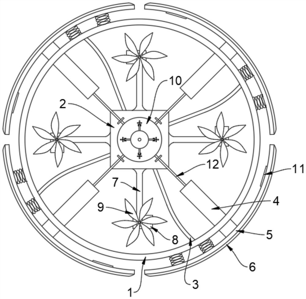
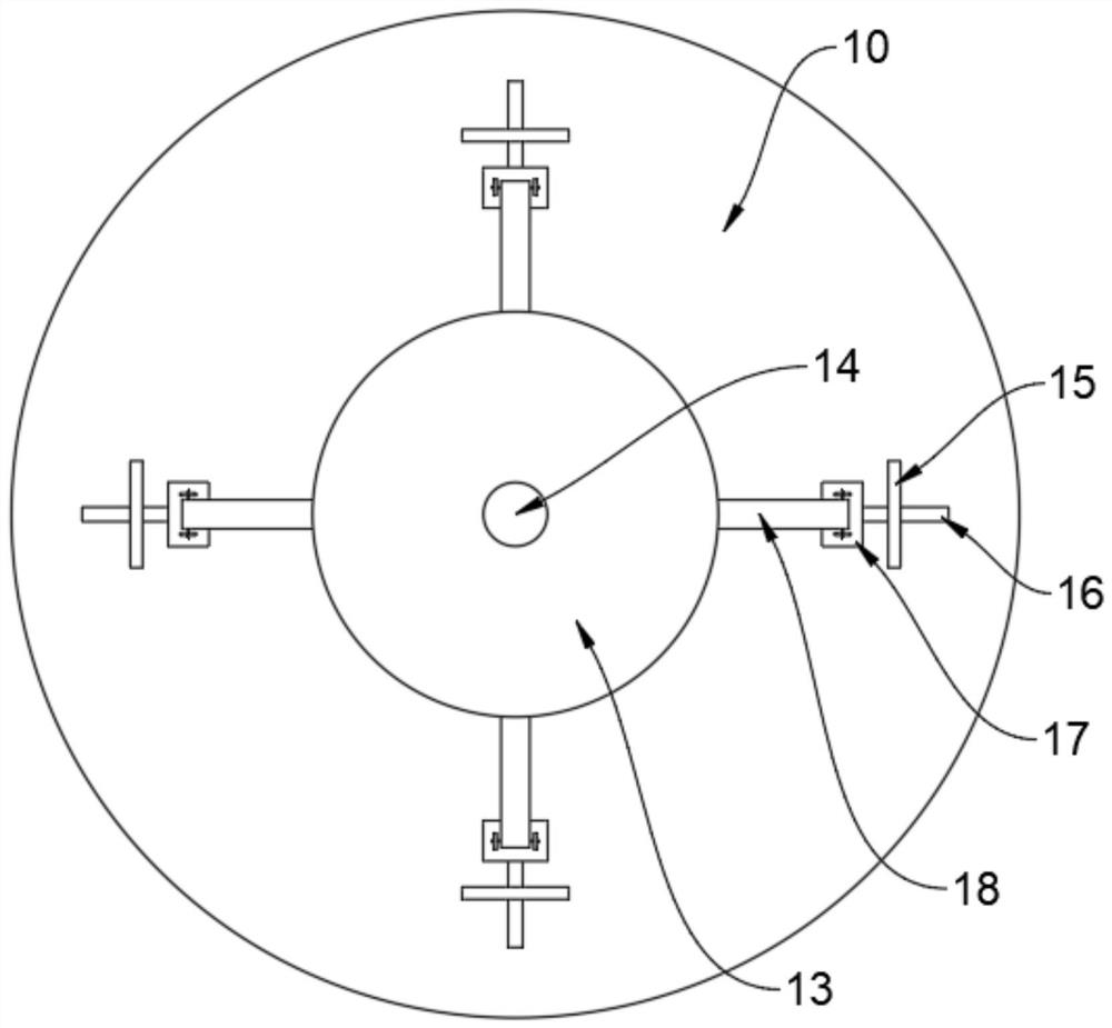
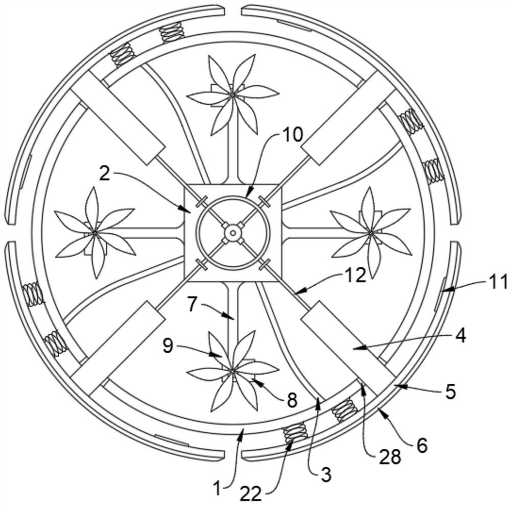
An unmanned aerial vehicle flight anti-collision device comprises an unmanned aerial vehicle body and a plurality of mounting plates evenly mounted on the outer side of the unmanned aerial vehicle body, and driving motors are arranged at the bottoms of the ends, away from the unmanned aerial vehicle body, of the mounting plates; output shafts of the driving motors upwards penetrate through the mounting plates where the output shafts are located and then are provided with a plurality of paddles in the circumferential direction, the exterior of the unmanned aerial vehicle body is connected with an external circular frame through a plurality of connecting frames arranged in the circumferential direction of the bottom of the unmanned aerial vehicle body, and a plurality of through holes c are formed in the periphery of the external circular frame in the circumferential direction. Collision protection of the unmanned aerial vehicle body, the mounting plate, the driving motor and the blades on the unmanned aerial vehicle is achieved through the combined action of counteracting cooperation of the reset mechanism in the cylindrical mounting shell and the arc plate and the buffering effect of the inflatable cushion outside the arc plate, and damage to main components on the miniature rotor unmanned aerial vehicle is avoided to the maximum extent; therefore, the accidental loss of the miniature rotor unmanned aerial vehicle in the flight process is reduced, and the economic loss of a user is greatly reduced.

Description

technical field [0001] The invention relates to the technical field of unmanned aerial vehicles, in particular to an anti-collision device for unmanned aerial vehicles. Background technique [0002] UAVs first appeared in the 1920s. In 1914, the First World War was in full swing. The two generals of the United Kingdom, Carder and Pitcher, made a suggestion to the British Military Aeronautical Society: develop a drone that does not use drones. It is a small aircraft piloted by humans and controlled by radio, so that it can fly over a certain target area of ​​​​the enemy and drop the bombs loaded on the small aircraft in advance. This bold idea was immediately appreciated by Sir Day Henderson, then chairman of the British Military Aviation Society. He appointed a team led by Professor A.M. Lowe to carry out the development. The UAV was used as a target aircraft for training at that time. It is a term used by many countries to describe the latest generation of unmanned aircraf...

Claims


Application Information

Patent Timeline
Patent Type & Authority Applications(China)
IPC IPC(8): B64C27/20B64D45/00F16F15/023
CPCB64C27/20B64D45/00F16F15/023B64U30/00B64U10/10
Inventor 王浩然
Owner 王浩然
Why Eureka
Try Eureka