
Three-plate-type composite die injection molding machine

A compound mold and injection molding machine technology, applied in the field of plastic machinery, can solve the problems of core board shaking and affecting production, and achieve the effects of reliable installation, increasing efficiency, and stable mold clamping.

Pending Publication Date: 2018-01-16
浙江力松机械有限公司
View PDF3 Cites 0 Cited by
  • Summary
  • Abstract
  • Description
  • Claims
  • Application Information

AI Technical Summary

Problems solved by technology

However, in actual production, since the core plate is directly installed on the frame, limited by the structure of the core plate itself, the core plate can only be fixed to the frame at the bottom without a backing (the existing cavity plate and the The core boards are installed by sticking to the fixed template and the moving template,) when the mold is opened and closed, the core board will shake, which will affect the production

Method used


Image

  • Three-plate-type composite die injection molding machine
  • Three-plate-type composite die injection molding machine
  • Three-plate-type composite die injection molding machine

Examples


Embodiment Construction

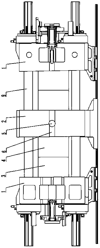
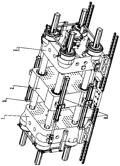
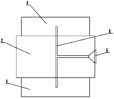
[0010] The invention relates to a three-plate compound mold injection molding machine, such as figure 1 — image 3 As shown, it includes two movable templates 1 and a fixed template 2 arranged on the frame of the injection molding machine, the fixed template 2 is arranged between the two movable templates 1, and the two movable templates 1 and one fixed template 2 are connected by a tie rod 9 Connection, set a core plate 3 of a mold on the inner side walls of the two movable formworks 1, set a cavity plate 4 of the mold on the two side walls of the fixed formwork 2, the cavity plate 4 and the core plate 3 Correspondingly, a side gate 5 is set on one side of the fixed formwork 2, a bidirectional hot runner 6 is set in the fixed formwork 2, the side gate 5 is connected to the bidirectional hot runner 6, and the bidirectional hot runner 6 is connected to two cavity plates 4 . The main feature of this scheme is that two movable formworks 1 and one fixed formwork 2 are arranged o...


PUM


Abstract

The invention discloses a three-plate-type composite die injection molding machine. The three-plate-type composite die injection molding machine comprises two movable templates and a fixed template which are arranged on a rack of the injection molding machine, wherein the fixed template is arranged between the two movable templates; the two movable templates are connected with the fixed template by a pull rod; a mold core plate of the mold is arranged on the inner side wall of each of the two movable templates; a mold cavity plate of the mold is arranged on each of two side walls of the fixedtemplate; the mold cavity plates are in two-to-two correspondence to the mold core plates; a side gate is arranged on one side of the fixed template; a two-way hot runner is arranged in the fixed template and is communicated with the side gate and the two mold cavity plates. Compared with an existing mode of directly arranging the mold cavity plates on the rack, the mode disclosed by the inventionhas the advantages that the mold core plates prop against the fixed template, and further are firmer to mount; particularly, the impact force is great when the mold is closed, the mold core plates lean against the fixed template and offset the impact force, so that the mold is closed more stably.

Description

technical field [0001] The invention relates to a three-plate compound mold injection molding machine, which belongs to the field of plastic machinery. Background technique [0002] Injection molding machine is a commonly used plastic machine for processing plastic products. The main structure includes injection part and template part. The template part of the existing injection molding machine mostly adopts two-plate type, that is, a fixed template and a movable template. The two templates are connected by tie rods. The cavity plate of the mold is installed on the fixed template, and the core plate of the mold is installed on the movable template The injection part is connected to the cavity plate through the injection hole on the fixed template. In order to improve production efficiency, the applicant once designed a compound mold injection molding machine, including installing a fixed template at both ends of the frame, connecting the two fixed templates with tie rods, ...

Claims


Application Information

Patent Timeline
Patent Type & Authority Applications(China)
IPC IPC(8): B29C45/12B29C45/67
Inventor 汪军建
Owner 浙江力松机械有限公司
Learn More