Tapping device for plug installation
A kind of installation and tapping technology, applied in the direction of assembly/disassembly of contacts, which can solve the problems of labor-intensive and low work efficiency.
- Summary
- Abstract
- Description
- Claims
- Application Information
AI Technical Summary
Problems solved by technology
Method used
Image
Examples
Embodiment 1
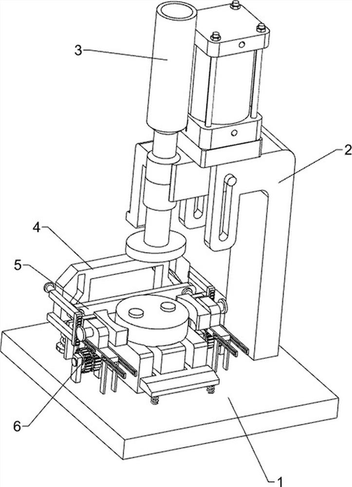
[0067] A tapping device for plug installation, such as figure 1 As shown, it includes a base 1, a lifting mechanism 2 and a knocking mechanism 3, the top of the base 1 is provided with a lifting mechanism 2, and the lifting mechanism 2 is provided with a knocking mechanism 3.
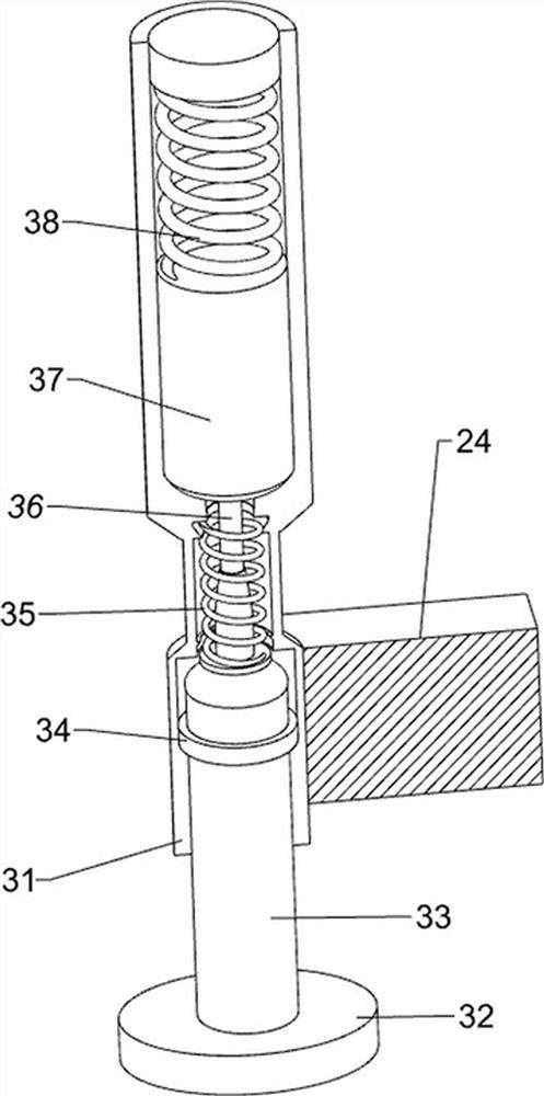
[0068]When people need to install a plug, they first put the bolt on a certain part of the lifting mechanism 2, then put the plastic head on the top of the bolt, and then start a certain part of the lifting mechanism 2, and the lifting mechanism 2 drives the knocking mechanism 3 to run. The knocking mechanism 3 knocks down on the plastic head, so that the plug is installed on the plastic head, and then manually removes the installed plug, puts in the next set of plug pins and plastic heads, and the device runs repeatedly. When all the plugs and plastic heads After all being installed into plug, close a certain part of lifting mechanism 2.
Embodiment 2
[0070] On the basis of Example 1, such as figure 2 , image 3 and Figure 4 As shown, the lifting mechanism 2 includes a first support column 21, a fixed plate 22, a cylinder 23, a first connecting block 24, a first slide bar 25 and a mounting platform 26, and the first support column 21 is arranged in the middle of the right side of the top of the base 1 , the left side of the top of the first support column 21 is provided with a fixed plate 22, the top of the fixed plate 22 is provided with a cylinder 23, the bottom of the cylinder 23 is provided with a first connecting block 24, and the right parts of the first connecting block 24 are provided with first Both the sliding bar 25 and the first sliding bar 25 are slidably connected to the upper left side of the first support column 21 , and a mounting platform 26 is arranged in the middle of the top of the base 1 .
[0071] When people need to install the plug, they first put the plug on the mounting table 26, then put the ...
Embodiment 3
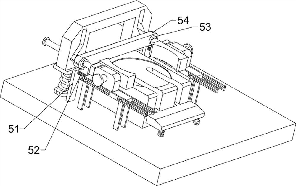
[0077] On the basis of Example 2, such as Figure 5 and Figure 6 As shown, a pusher mechanism 5 is also included. The pusher mechanism 5 includes a third support column 51, a fourth spring 52, a block 53 and a baffle plate 54. The rear side of the top of the base 1 is symmetrically provided with a third support column 51. , the third support columns 51 are all located at the front side of the limit support column 410 on the same side, and the fourth spring 52 is arranged between the upper part of the front side of the third support column 51 and the rear side of the first bottom plate 44 on the same side, and the fourth slide Two clamping blocks 53 are arranged on the front parts of the rods 49 , and a baffle 54 is arranged between the front parts of the fourth sliding rod 49 , and the baffles 54 are located between the clamping blocks 53 .
[0078] After the latch is installed on the plastic head, the fourth slide bar 49 is manually pushed forward, and the fourth slide bar ...
PUM
 Abstract
Description
Claims
Application Information
 - R&D
- Intellectual Property
- Life Sciences
- Materials
- Tech Scout
- Unparalleled Data Quality
- Higher Quality Content
- 60% Fewer Hallucinations
Browse by: Latest US Patents, China's latest patents, Technical Efficacy Thesaurus, Application Domain, Technology Topic, Popular Technical Reports.
© 2025 PatSnap. All rights reserved.Legal|Privacy policy|Modern Slavery Act Transparency Statement|Sitemap|About US| Contact US: help@patsnap.com


