Industrial chemical experiment table

A technology for chemical experiments and test benches, used in laboratory stools/lab benches, laboratory utensils, chemical instruments and methods, etc., can solve the problems of inconvenient access and unstable center of gravity of chemical material bottles, and achieve uniform force. Effect

Inactive Publication Date: 2021-05-25
陈明
View PDF7 Cites 0 Cited by
  • Summary
  • Abstract
  • Description
  • Claims
  • Application Information

AI Technical Summary

Problems solved by technology

[0003] Since there is a storage cabinet installed under the test bench, it is used to store chemical material bottles that cannot be exposed to light for a long time. When the chemical material bottles are taken and placed, the material is placed in a deep position. Transfer to the inside of the storage cabinet. When transferring, the hands are stretched out, which makes the center of gravity of the chemical material bottle unstable, resulting in inconvenient access.

Method used


Image

  • Industrial chemical experiment table
  • Industrial chemical experiment table
  • Industrial chemical experiment table

Examples


Embodiment 1

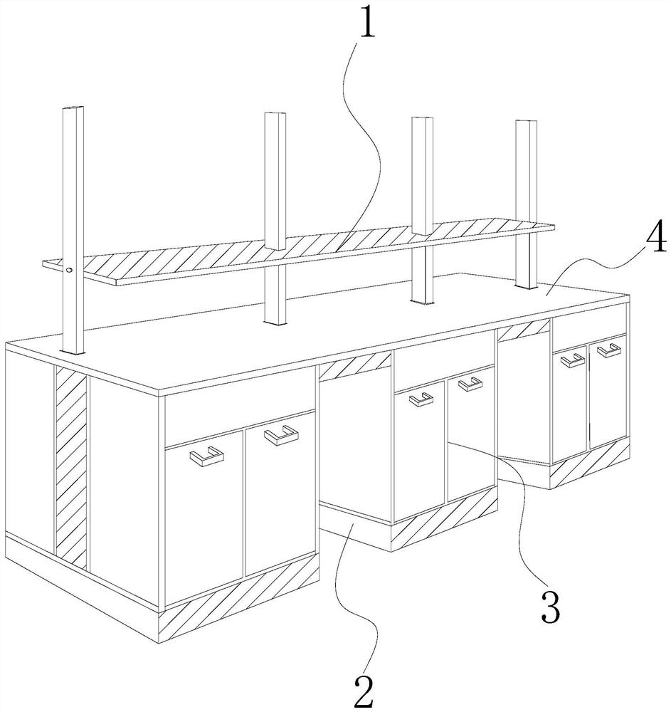
[0026] Such as Figure 1-Figure 5 Shown:

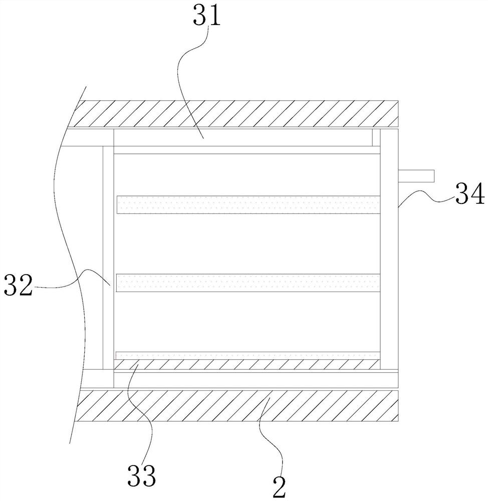
[0027] The present invention is an industrial chemical experiment platform, the structure of which includes a placement frame 1, a support platform 2, and a storage mechanism 3. The placement frame 1 is embedded in the upper end of the experiment platform 4, and the experiment platform 4 is attached to the upper end of the support platform 2. The storage mechanism 3 is installed inside the support platform 2, the storage mechanism 3 is provided with a fixed plate 31, a buffer plate 32, a sliding track 33, and a translation mechanism 34, and the buffer plate 32 is embedded in the fixed plate 31. The sliding track 33 is installed on the bottom side of the fixed plate 31, the lower end side of the translation mechanism 34 is in clearance fit with the sliding track 33, the fixed plate 31 is installed inside the support platform 2, and the right side of the buffer plate 32 is made of sponge material. It has the characteristics of strong c...

Embodiment 2

[0034] Such as Figure 6-Figure 8 Shown:

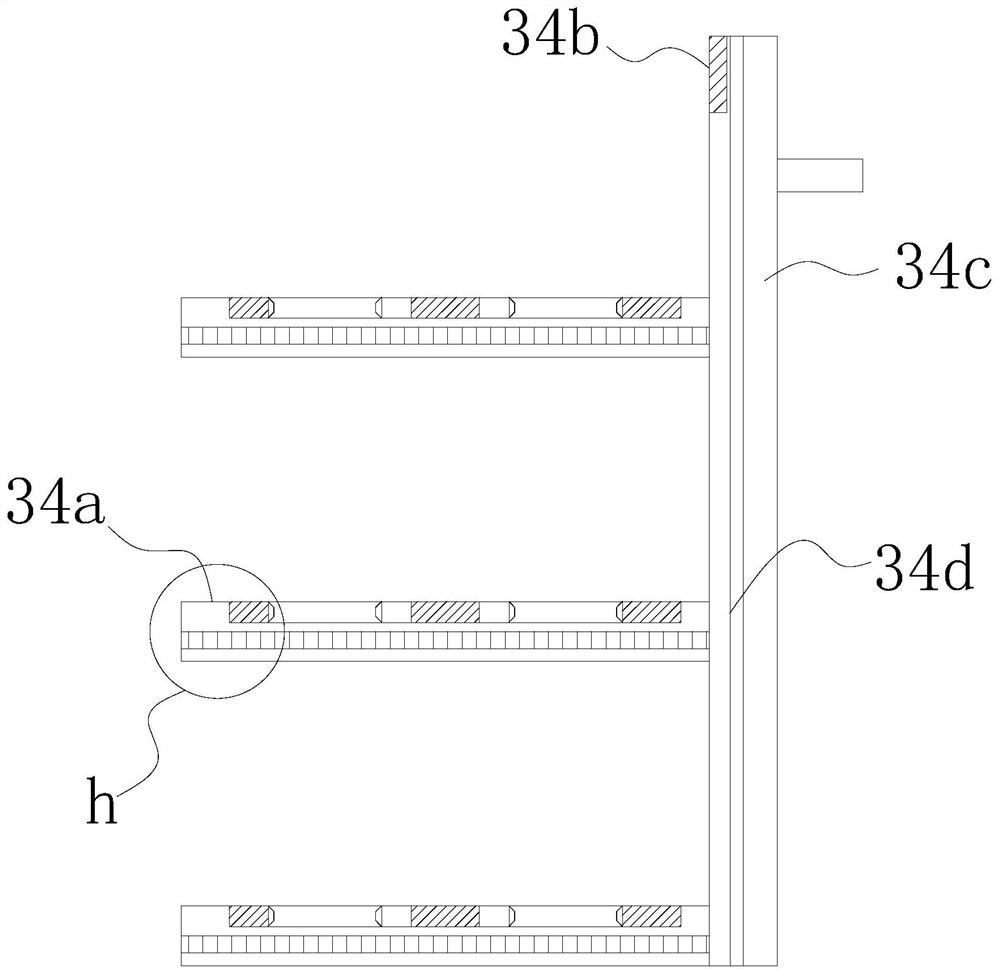
[0035] Wherein, the fixing mechanism 34a is provided with a friction plate a1, an engaging mechanism a2, and a sliding groove a3. The engaging mechanism a2 is embedded on the upper surface of the friction plate a1, and the sliding groove a3 is installed inside the friction plate a1. The right side of the friction plate a1 is embedded and fixed on the left side of the sliding mechanism 34d. The surface of the friction plate a1 is an inwardly sunken structure, which has the effect of fixing the chemical material and prevents the sliding mechanism 34d from causing the chemical material bottle to slide due to excessive inertial force when pushing. .

[0036]Wherein, the engaging mechanism a2 is provided with a compression plate a21, a bonding mechanism a22, and a curved plate a23, the curved plate a23 is bonded to the inside of the compression plate a21, and the curved plate a23 is welded to the inside of the bonding mechanism a22, so T...


PUM


Abstract

The invention discloses an industrial chemical experiment table which structurally comprises a placing frame, a supporting table and a storage mechanism. The placing frame is fixedly embedded in the upper end of an experiment table, the experiment table is attached to the upper end of the supporting table, and the storage mechanism is installed in the supporting table. The storage mechanism in the supporting table is pushed and pulled so as to enable a translation mechanism to drive a buffer plate to slide in a sliding rail in parallel, and meanwhile, a cabinet door drives a fixing mechanism to translate, so that the right side of the supporting mechanism and the left side of a lever plate slide on a sliding plate, chemical material bottles with different heights are reasonably placed, the situation that the two hands need to take and place the chemical material bottles in the supporting table is avoided, and the situation that the chemical material bottles are inconvenient to take and place due to the fact that the fixing mechanism is arranged in the supporting table is avoided. The chemical material bottles are placed on the surface of a friction plate, meanwhile, an attaching plate enables the chemical material bottles to be evenly stressed, and the chemical material bottles fixed in a clamping mechanism are fixed, so that the chemical material bottles are prevented from sliding and toppling due to inertia force generated when a sliding groove slides in the sliding rail.

Description

technical field [0001] The invention relates to the field of industrial chemistry, in particular to an industrial chemical experiment bench. Background technique [0002] The test bench is used for the placement of chemical experiment tools. The surface of the test bench is made of anti-corrosion marble material to avoid damage to the test bench by the poured liquid during the chemical experiment. There are shelves for fixed placement of various glass containers. [0003] Since there is a storage cabinet installed under the test bench, it is used to store chemical material bottles that cannot be exposed to light for a long time. When the chemical material bottles are taken and placed, the material is placed in a deep position. When transferring to the inside of the storage cabinet, the hands are stretched out during the transfer, which makes the center of gravity of the chemical material bottle unstable, resulting in the problem of inconvenient access. Contents of the inv...

Claims


Application Information

Patent Timeline
Patent Type & Authority Applications(China)
IPC IPC(8): B01L9/02B01L9/00
CPCB01L9/00B01L9/02
Inventor 陈明
Owner 陈明
Why Eureka
Try Eureka