Supercharge Your Innovation With Domain-Expert AI Agents!

Push rod locking mechanism and hydraulic support

A technology of locking mechanism and hydraulic support, which is applied in mine roof supports, mining equipment, earthwork drilling and mining, etc., can solve the problems of unsightly appearance and professionalism, damage of push rods, etc., and achieve the effect of strong applicability

Pending Publication Date: 2021-05-25
SANY HEAVY EQUIP
View PDF0 Cites 0 Cited by
  • Summary
  • Abstract
  • Description
  • Claims
  • Application Information

AI Technical Summary

Problems solved by technology

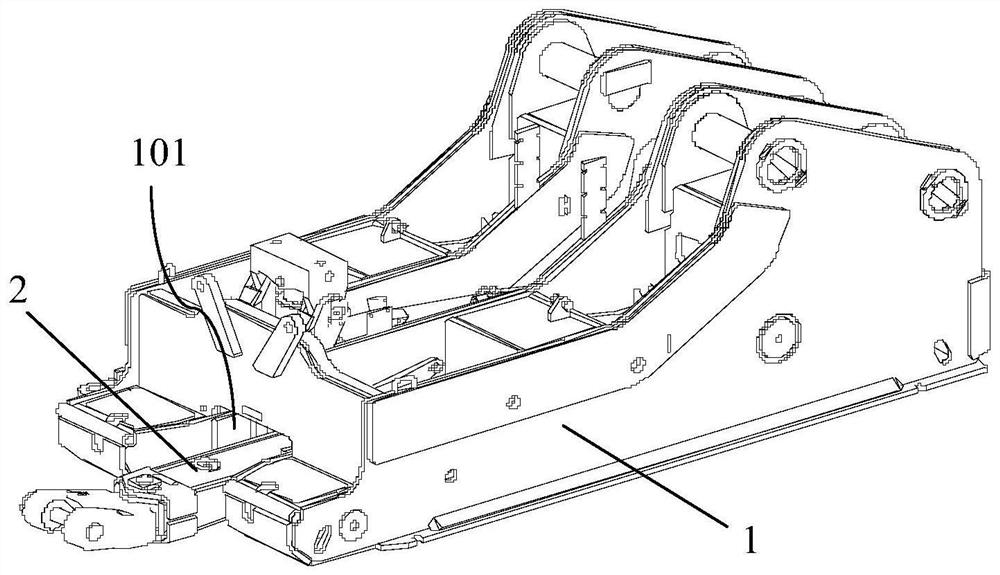
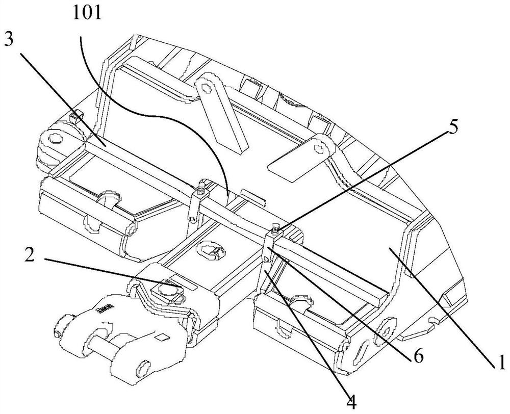
In order to protect the oil cylinder during the transportation of the pushing device, the pushing device is generally lifted and fixed on the base. The usual solution is to pass the profile through the lifting ring on the push rod, and put the two ends on the front end of the base, or directly use The iron wire connects the push rod to the base, and the scheme of using the profile to pass through the lifting ring on the push rod often encounters that the push rod will touch the bridge when it is lifted, which may easily cause damage to the push rod, and for those without welding rings The push rod is not suitable; and although the scheme of directly connecting the push rod and the base with iron wire is simple and economical, it is not beautiful and professional to bind the push rod with iron wire. Therefore, a suitable and beautiful push rod transport locking mechanism is urgently needed Research

Method used


Image

  • Push rod locking mechanism and hydraulic support
  • Push rod locking mechanism and hydraulic support
  • Push rod locking mechanism and hydraulic support

Examples


Embodiment Construction

[0040] In describing the present invention, it should be understood that the terms "center", "longitudinal", "transverse", "length", "width", "thickness", "upper", "lower", "front", " Orientation or position indicated by "back", "left", "right", "vertical", "horizontal", "top", "bottom", "inner", "outer", "clockwise", "counterclockwise", etc. The relationship is based on the orientation or positional relationship shown in the drawings, and is only for the convenience of describing the present invention and simplifying the description, rather than indicating or implying that the referred device or element must have a specific orientation, be constructed and operated in a specific orientation, therefore It should not be construed as a limitation of the present invention.

[0041] In addition, the terms "first" and "second" are used for descriptive purposes only, and cannot be interpreted as indicating or implying relative importance or implicitly specifying the quantity of indic...


PUM


Abstract

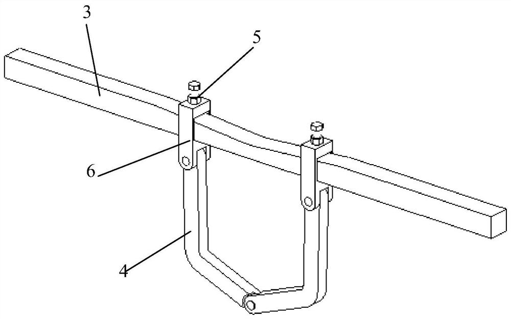
The invention discloses a push rod locking mechanism and a hydraulic support. According to the push rod locking mechanism, the distance between the second ends of two bent rods on a supporting rod is adjusted, so that a push rod can be sleeved with a polygon formed by the supporting rod and the two bent rods; then the second ends of the two bent rods are fixed to the supporting rod through limiting assemblies, so that the push rod is locked by the supporting rod and the two bent rods and hoisted on a base; and the first ends of the two bent rods are hinged, so that the two bent rods rotate relative to each other, and then push rods of different types can be sleeved with the polygon formed by the supporting rod and the two bent rods. Thus, the push rod locking mechanism is high in applicability and attractive.

Description

technical field [0001] The invention belongs to the technical field of hydraulic supports, and in particular relates to a push rod locking mechanism and a hydraulic support. Background technique [0002] The hydraulic support is the main support equipment for the underground fully mechanized coal mining face. It mainly includes the top beam, the cover beam and the base. The element is an oil cylinder. In order to protect the oil cylinder during the transportation of the pushing device, the pushing device is generally lifted and fixed on the base. The usual solution is to pass the profile through the lifting ring on the push rod, and put the two ends on the front end of the base, or directly use The iron wire connects the push rod to the base, and the scheme of using the profile to pass through the lifting ring on the push rod often encounters that the push rod will touch the bridge when it is lifted, which may easily cause damage to the push rod, and for those without weldi...

Claims


Application Information

Patent Timeline
Patent Type & Authority Applications(China)
IPC IPC(8): E21D23/18E21D23/08
CPCE21D23/18E21D23/08
Inventor 魏来孙晓亮朱庆波赵忠志王鹏
Owner SANY HEAVY EQUIP
Features
  • R&D
  • Intellectual Property
  • Life Sciences
  • Materials
  • Tech Scout
  • Unparalleled Data Quality
  • Higher Quality Content
  • 60% Fewer Hallucinations
Learn More