Unlock instant, AI-driven research and patent intelligence for your innovation.
Computer room inspection camera and inspection method
What is Al technical title?
Al technical title is built by PatSnap Al team. It summarizes the technical point description of the patent document.
A computer room and camera technology, which is applied in the computer field, can solve the problem that the monitoring of the computer room is not easy to monitor the dead angle, etc., and achieve the effect of rich inspection routes and single angle compensation.
Active Publication Date: 2021-07-30
HARBIN UNIV
View PDF0 Cites 0 Cited by
Summary
Abstract
Description
Claims
Application Information
AI Technical Summary
This helps you quickly interpret patents by identifying the three key elements:
Problems solved by technology
Method used
Benefits of technology
Problems solved by technology
[0004] The purpose of the present invention is to solve the problem that existing computer room monitoring is not easy to monitor dead angles, and provides a computer room inspection camera and inspection method
Method used
Image
Click on the blue label to locate the original text in one second.
Reading with bidirectional positioning of images and text.
Examples
specific Embodiment approach 1
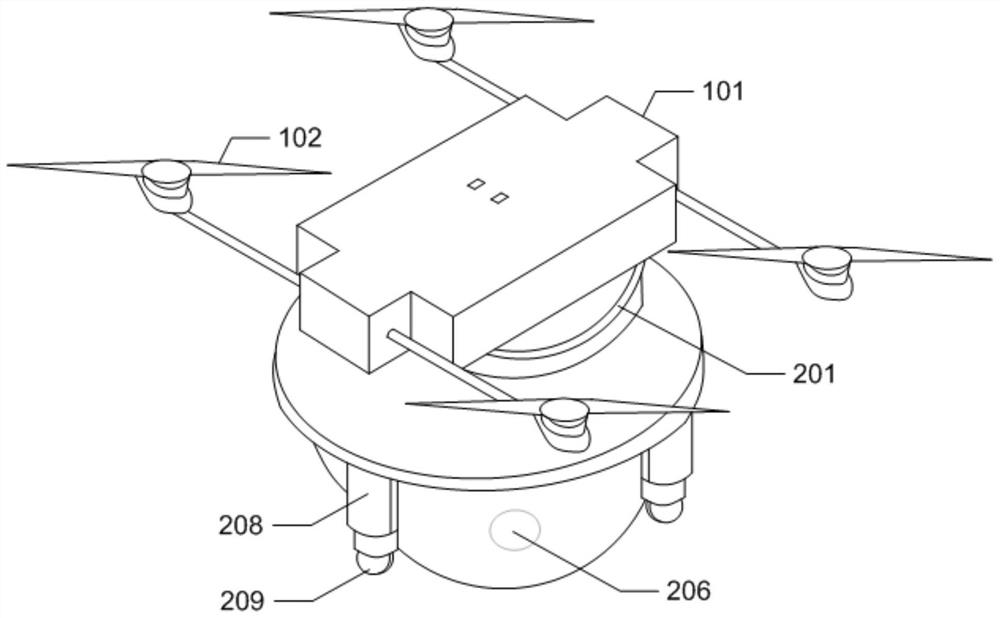
[0035] DETAILED DESCRIPTION One: Bindings figure 1 In the present embodiment, the computer computer room inspection imaging, including a charging seat, a flight unit, and a monitoring unit; the charge holder is disposed on the roof of the machine room, the flight unit and the monitoring unit are fixed together and suck the charge seat. ;
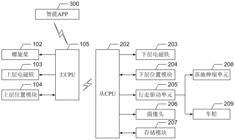
[0036] The flying unit includes an upper adapter plate 101, and four propellers 102 are provided on both sides of the upper adapter plate 101; the upper surface of the upper surface of the upper adapter plate 101 is provided with a charging electrode point matching the charge holder; the upper surface of the upper surface is adjacent to the upper surface. The upper electromagnet 103 is used to absorb the ferrule of the charge seat; the upper surface of the upper surface of the upper surface is disposed adjacent to the lower surface, and the upper layer adapter plate 101 is also provided with the main CPU 105 and the upper layer position module 1...
specific Embodiment approach 2
[0047] DETAILED DESCRIPTION 2: Bonding below figure 2 Description This embodiment, the computer room inspection method of the present embodiment includes two categories: flight inspection and ground inspection, all by intelligent App300 control. It can be a timed inspection or a person to check the instructions for people.
[0048] Flight Patrol Steps:
[0049] Step 1, the intelligent app300 sends a flight inspection instruction to the main CPU 105;
[0050] Step 2, the main CPU 105 receives the flight inspection instruction, first start the propeller 102;
[0051] Step three, the main CPU 105 releases the upper electromagnet 103, and the flight unit is detached from the charging seat;
[0052] Step 4, the flight unit carries the monitoring unit according to the flight inspection planning route inspection in the machine room, and the location information of the flight inspection is determined according to the upper layer position module 104 within the flight unit;
[0053] Step 4'...
PUM
Abstract
The computer room inspection camera and inspection method belong to the field of computers, and the invention solves the problem that the existing computer room monitoring is not easy to monitor dead angles. The inspection camera of the present invention includes a charging base, a flying unit and a monitoring unit; the charging base is arranged on the roof of the machine room, and the flying unit and the monitoring unit are fixed together and sucked on the charging base; the flying unit includes an upper connecting plate, an upper electromagnet and four propellers; the main CPU controls the start-stop and hovering operations of the propellers, and the main CPU controls the on-off state of the upper electromagnet; the monitoring unit includes a lower connection board, a slave CPU202, a lower electromagnet, a lower position module and a storage module ; The lower surface of the lower connecting plate is provided with a monitoring cover, and a plurality of cameras are arranged inside the monitoring cover; the information of the monitoring unit is fed back to the main CPU from the CPU. The invention can carry out flight inspection and ground inspection.
Description
Technical field [0001] The present invention relates to a patrol technology, which is a computer room, which belongs to the computer area. Background technique [0002] With the continuous development of information technology, computer houses have become an important part of major enterprises. Computer equipment has high requirements for temperature, humidity, cleanliness, etc., once the room environment equipment is faulty, it will affect computer The system is running. [0003] Most computer rooms are not in place, but often is not in place, while the seminar management is not in place. For example, dust is blocked, for example, long, large-scale open floors leads to short air flow, and the upper equipment of the cabinet cannot be blown up. It is raised by high, such as debris such as plastic foam to fill into air conditioners. In order to prevent the occurrence of these faults, monitoring the camera is required to monitor the camera to complete the monitoring task, but there ...
Claims
Application Information
Patent Timeline
Application Date:The date an application was filed.
Publication Date:The date a patent or application was officially published.
First Publication Date:The earliest publication date of a patent with the same application number.
Issue Date:Publication date of the patent grant document.
PCT Entry Date:The Entry date of PCT National Phase.
Estimated Expiry Date:The statutory expiry date of a patent right according to the Patent Law, and it is the longest term of protection that the patent right can achieve without the termination of the patent right due to other reasons(Term extension factor has been taken into account ).
Invalid Date:Actual expiry date is based on effective date or publication date of legal transaction data of invalid patent.

