Antenna structure and terminal equipment

A technology of antenna structure and terminal equipment, applied in the field of communication, can solve the problems of narrow bandwidth and low radiation efficiency, and achieve the effect of improving radiation efficiency and working bandwidth, and increasing radiation path.

Active Publication Date: 2021-05-25
BEIJING XIAOMI MOBILE SOFTWARE CO LTD
View PDF10 Cites 0 Cited by
  • Summary
  • Abstract
  • Description
  • Claims
  • Application Information

AI Technical Summary

Problems solved by technology

When transmitting and receiving wireless signals in the 6GHz to 9GHz frequency band, multiple radiators in traditional antennas have the problems of low radiation efficiency and narrow bandwidth when transmitting and receiving wireless signals

Method used


Image

  • Antenna structure and terminal equipment
  • Antenna structure and terminal equipment
  • Antenna structure and terminal equipment

Examples


Embodiment Construction

[0039] Reference will now be made in detail to the exemplary embodiments, examples of which are illustrated in the accompanying drawings. When the following description refers to the accompanying drawings, the same numerals in different drawings refer to the same or similar elements unless otherwise indicated. The implementations described in the following exemplary examples do not represent all implementations consistent with the present invention. Rather, they are merely examples of apparatuses and methods consistent with aspects of the invention as recited in the appended claims.

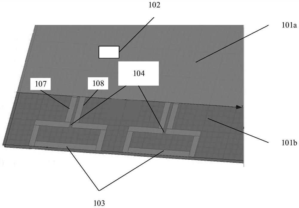
[0040] Figure 1a is a schematic diagram 1 of an antenna structure shown according to an exemplary embodiment. like Figure 1a As shown, the antenna structure includes at least:

[0041] a substrate having a first region 101a and a second region 101b coplanar with the first region 101a;

[0042] a radio frequency module 102, located on the first area 101a;

[0043] At least two antenna radiat...


PUM


Abstract

The invention relates to an antenna structure and terminal equipment. The antenna structure comprises: a substrate, having a first region and a second region coplanar with the first region; a radio frequency module located on the first area; and at least two antenna radiators located in the second area, wherein each antenna radiator comprises an opening defined by at least two side edges, one end of the opening is connected with the radio frequency module through a first slot line, the other end of the opening is connected with a ground wire through a second slot line, and the first slot line is parallel to the second slot line. According to the embodiment of the invention, the first slot line and the second slot line can radiate the wireless signal while transmitting the wireless signal, so that the radiation path of the wireless signal can be increased, and the radiation efficiency and the working bandwidth of the antenna structure can be improved.

Description

technical field [0001] The present disclosure relates to the technical field of communications, and in particular, to an antenna structure and a terminal device. Background technique [0002] With the rapid development of communication technology and the demand for technology, the bandwidth of terminal equipment is getting wider and wider, and the frequency of sending and receiving wireless signals is getting higher and higher. For example, the frequency of transmitting and receiving wireless signals of terminal equipment gradually develops from 450MHz-960MHz to 1.8GHz, 2.1GHz, 2.4GHz, 3.5GHz and 5GHz; and transitions from 5GHz to Ultra-Wide band (UWB) 6GHz to 9GHz. When transmitting and receiving wireless signals in the 6GHz to 9GHz frequency band, traditional antennas with multiple radiators have the problems of low radiation efficiency and narrow bandwidth when transmitting and receiving wireless signals. Contents of the invention [0003] The present disclosure provid...

Claims


Application Information

Patent Timeline
Patent Type & Authority Applications(China)
IPC IPC(8): H01Q1/38H01Q1/48H01Q1/50H01Q1/22H01Q1/24
CPCH01Q1/38H01Q1/50H01Q1/48H01Q1/242H01Q1/2258
Inventor 胡茂程胜祥
Owner BEIJING XIAOMI MOBILE SOFTWARE CO LTD
Why Eureka
Try Eureka