
Antenna for controlling a direction of a radiation pattern

A technology of antenna and radiating components, which is applied to antenna unit combinations, antennas, antenna arrays and other directions with different polarization directions, and can solve problems such as radiating the main beam

Inactive Publication Date: 2010-08-25
ACE TECH
View PDF6 Cites 1 Cited by
  • Summary
  • Abstract
  • Description
  • Claims
  • Application Information

AI Technical Summary

Problems solved by technology

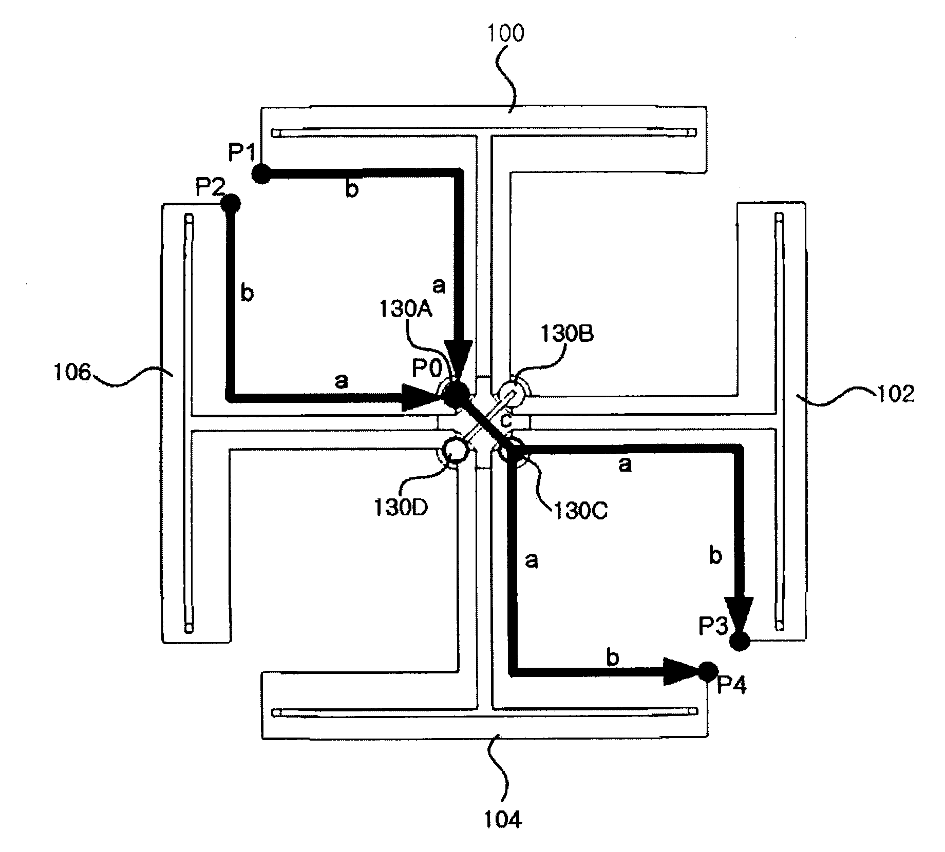
[0015] Therefore, there is a problem that the major axis 300 of the +45° polarization produced by the dipole assemblies 100, 102, 104, 106 is shifted to the right of the +45° axis 302, as shown in FIG.
As a result, it is difficult to radiate the main beam in the desired direction
In particular, such shifting phenomenon of the radiation pattern in the low frequency band is more severe than that of the radiation pattern in the high frequency band

Method used


Image

  • Antenna for controlling a direction of a radiation pattern
  • Antenna for controlling a direction of a radiation pattern
  • Antenna for controlling a direction of a radiation pattern

Examples


Embodiment Construction

[0058] Example embodiments of the invention are disclosed herein. However, specific structural and functional details disclosed herein are merely representative for purposes of describing example embodiments of the invention which, however, may be embodied in many alternative forms and should not be construed are limited to the example embodiments of the invention set forth herein.

[0059] Therefore, while the invention is capable of various modifications and alternative forms, specific embodiments of the invention are shown by way of example in the drawings and will be described in detail herein. It should be understood, however, that there is no intent to limit the invention to the particular forms disclosed, but on the contrary, the intention is to cover all modifications, equivalents, and alternatives falling within the spirit and scope of the invention. In the description of the drawings, the same reference numerals refer to the same elements throughout.

[0060] It wi...


PUM


Abstract

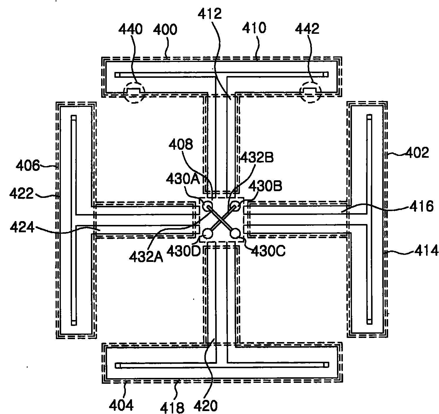
An antenna for compensating a phase of a current passing to a dipole member so as to prevent a shift phenomenon of a radiation pattern is disclosed. The antenna includes dipole members, and a feeding section connected to the dipole members, and configured to have at least two feeding points for providing current inputted from an outside device to the dipole members. Here, a first feeding point of the feeding points is connected to a second feeding point of the feeding points, the current is provided to the second feeding point through the first feeding point, and at least one of a slit and a projection member is formed to one or more of the dipole members.

Description

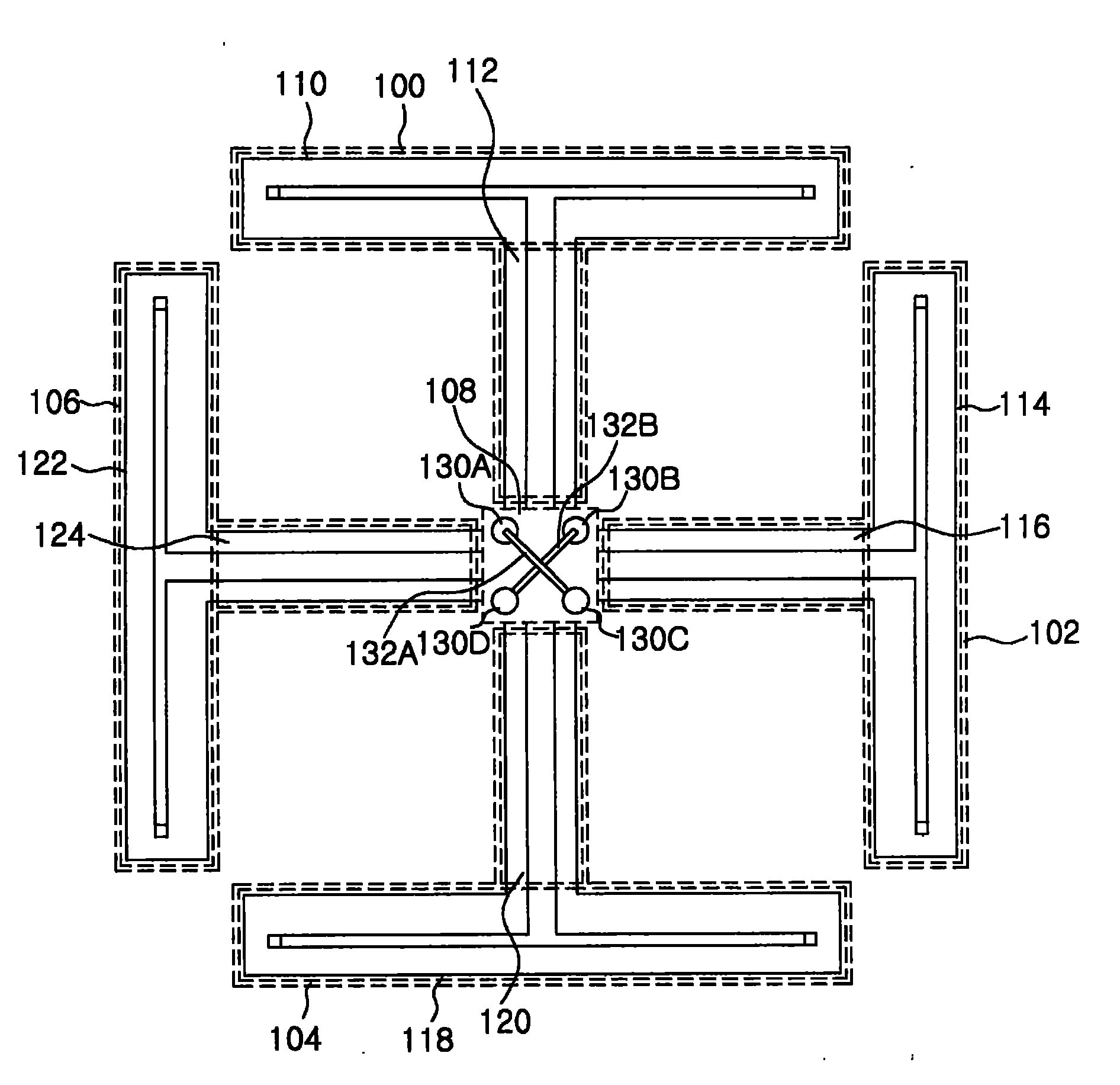
technical field [0001] Exemplary embodiments of the present invention relate to an antenna, and more particularly, to an antenna that compensates a phase of a current flowing through a dipole member to prevent a shift phenomenon of a radiation pattern. antenna. Background technique [0002] An antenna transmits or receives electromagnetic waves by radiating a radiation pattern, and generally has the following structure shown in FIG. 1 . [0003] Fig. 1 is a plan view of a common antenna. [0004] 1, the antenna produces dual polarization (dual polarization), and includes a first dipole assembly 100, a second dipole assembly 102, a third dipole assembly 104, a fourth dipole assembly 106, and a feeding section (feedingsection) 108. [0005] The feed section 108 has a first feed point 130A, a second feed point 130B, a third feed point 130C, a fourth feed point 130D, a first connection line 132A, and a second connection line 132B. [0006] The first feeding point 130A is con...

Claims


Application Information

Patent Timeline
Patent Type & Authority Applications(China)
IPC IPC(8): H01Q3/30
CPCH01Q9/26H01Q9/16H01Q3/30H01Q21/26H01Q3/44H01Q21/062
Inventor 郑泌奎李昇哲任起男
Owner ACE TECH
Learn More