Difference Compensation Mechanism Applied to Manipulator

A technology of compensation mechanism and manipulator, which is applied in the field of medical equipment, can solve the problems that cannot be applied in the medical field, and achieve the effect of flexible operation

Active Publication Date: 2022-06-03
HANGZHOU KANGJI MEDICAL INSTR
View PDF13 Cites 0 Cited by
  • Summary
  • Abstract
  • Description
  • Claims
  • Application Information

AI Technical Summary

Problems solved by technology

[0004] This invention patent application has the advantages of small size, light weight, strong flexibility, not easy to damage branches and leaves, and high degree of freedom of movement between complex branches and leaves, but it still has the above problems and cannot be applied in the medical field

Method used


Image

  • Difference Compensation Mechanism Applied to Manipulator
  • Difference Compensation Mechanism Applied to Manipulator
  • Difference Compensation Mechanism Applied to Manipulator

Examples


Embodiment Construction

[0028] The present invention will be described in further detail below in conjunction with the accompanying drawings and specific embodiments.

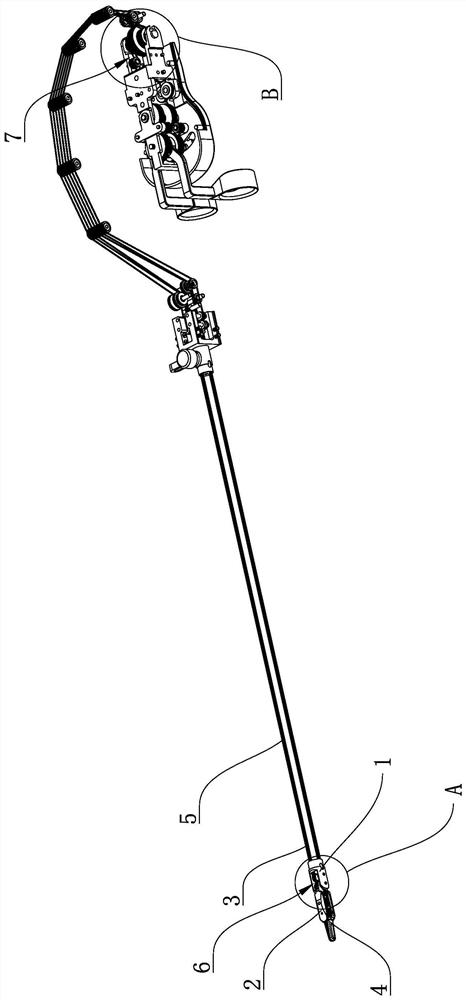
[0030] The forceps assembly 4 can be rotated under the pulling control of the second control rope 5. But the forceps are often not only

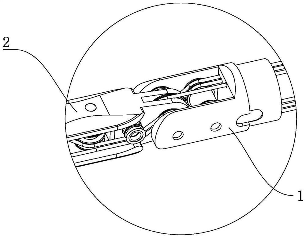
[0037] The first control rope 3 and the rotating assembly 2, the second control rope 5 and the forceps head assembly 4 can be connected to each other

[0041] Preferably, an anti-interference step 45 extends from the outer edge of the second rotating wheel 43 and / or the third rotating wheel 44. This

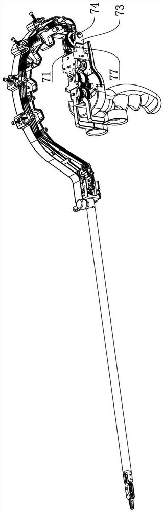
[0043] Preferably, the axis of the second tensioning wheel 62 coincides with the axis of rotation of the rotating assembly 2. i.e. the second tension

[0047] The specific embodiments described herein are merely illustrative of the spirit of the invention. The technical field to which the present invention belongs

[0048] Although the forceps head seat 1, the rotating assembly 2, the first control rope...


PUM


Abstract

The invention belongs to the technical field of medical devices, in particular to a difference compensation mechanism applied to a manipulator. The present invention aims at the problem in the prior art that the steel wire rope will be tightened or loosened when other positions are moved, thus causing the steel wire rope to drive the pincer head to have a slight positional deviation, and the independent control of the pincer head cannot be realized, which is inconvenient for medical staff to operate , providing a differential compensation mechanism applied to a manipulator, including a clamp seat, a clamp assembly, a second control rope and a tension wheel assembly, and a differential compensation assembly. During rotation, the second control rope is pressed on the The changing trend of the length of the difference compensation assembly is opposite to the changing trend of the length of the second control rope pressed on the tensioning wheel assembly. The present invention is equipped with a difference compensation component, and the tension or slack caused by the change of the length of the second control rope due to the pressure on the surface of the tension wheel component will be compensated and offset by the difference compensation component to ensure that the clamp head component is independently controlled.

Description

Difference Compensation Mechanism Applied to Manipulator technical field [0001] The present invention belongs to the technical field of medical devices, in particular to a difference compensation mechanism applied to a manipulator. Background technique [0002] Surgical forceps are mostly used in medicine to clamp human tissue during surgery. In the prior art, there is a wire rope control pliers Surgical forceps for head rotation and opening and closing. However, there are many movable joints set on the forceps, and the movable position is not limited to the forceps head. At one place, the wire rope will be tightened or loosened when moving other positions, which will cause the wire rope to drive the pliers head to slightly sag. The position of the device is offset, and the independent control of the forceps head cannot be realized, which is inconvenient for medical staff to operate. For example, Chinese invention patent application discloses a kind of detachable lap...

Claims


Application Information

Patent Timeline
Patent Type & Authority Patents(China)
IPC IPC(8): A61B34/00A61B34/30A61B17/29
CPCA61B34/70A61B34/30A61B17/29A61B2034/302A61B2017/2927
Inventor 钟鸣周宝红刘男程达
Owner HANGZHOU KANGJI MEDICAL INSTR
Why Eureka
Try Eureka