
Current testing device, current testing method and electronic equipment

A technology of current testing and sampling current, applied in the direction of measuring device, measuring current/voltage, measuring only current, etc., can solve the problems of test current conversion, test accuracy cannot test current conversion, and the test process is cumbersome, so as to ensure accurate measurement. Effect

Pending Publication Date: 2021-05-28
GUANGZHOU XIAOPENG MOTORS TECH CO LTD
View PDF10 Cites 1 Cited by
  • Summary
  • Abstract
  • Description
  • Claims
  • Application Information

AI Technical Summary

Problems solved by technology

[0002] In the related art, for the same current testing device, its range is usually fixed, and the range cannot be changed according to the size of the test current, and the test accuracy of the current test device is also fixed, and the test accuracy cannot be adjusted according to the size of the test current. transformation
When the fluctuation range of the sampling current is large, in order to ensure accurate measurement of currents of different magnitudes, it is necessary to replace the current testing device with different ranges, and the testing process is cumbersome.

Method used


Image

  • Current testing device, current testing method and electronic equipment
  • Current testing device, current testing method and electronic equipment
  • Current testing device, current testing method and electronic equipment

Examples


Embodiment Construction

[0027] Embodiments of the present application are described in detail below, examples of which are shown in the drawings, wherein the same or similar reference numerals denote the same or similar elements or elements having the same or similar functions throughout. The embodiments described below by referring to the figures are exemplary, and are intended to explain the present application, and should not be construed as limiting the present application.

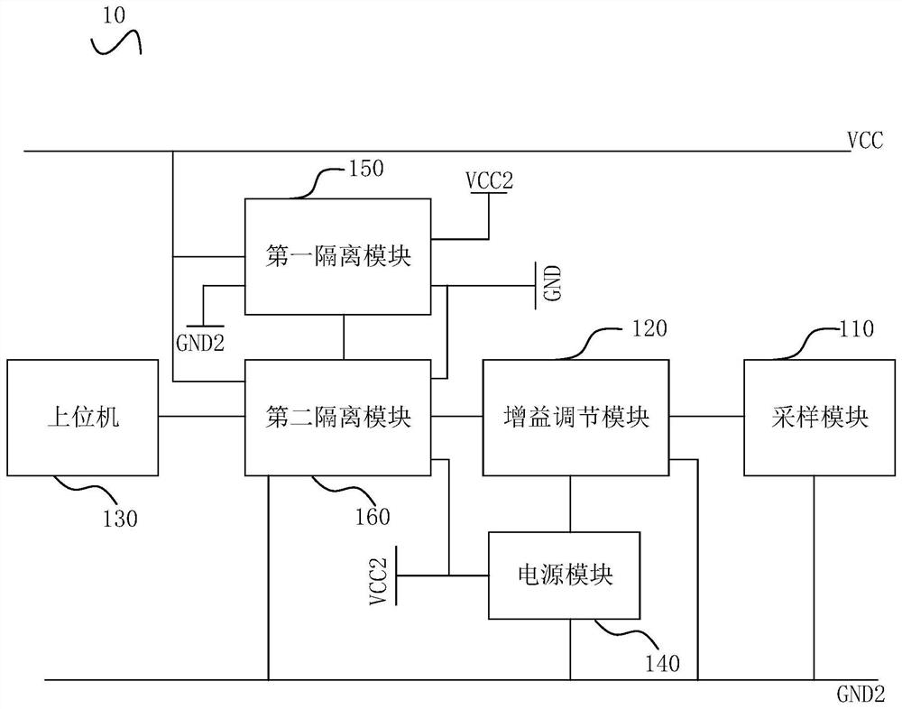
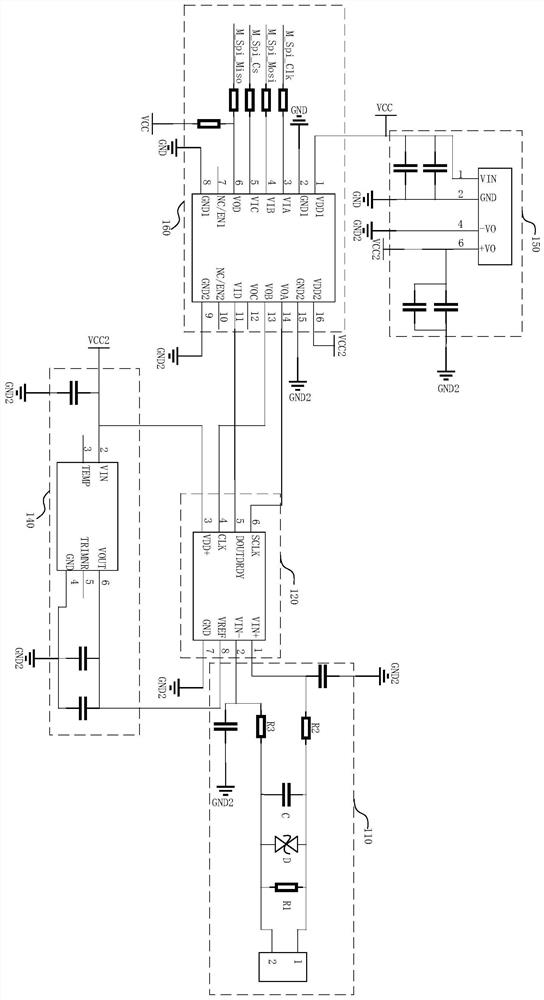
[0028] Please also refer to figure 1 with figure 2 , the embodiment of the present application provides a current test device 10 , the current test device 10 includes a sampling module 110 , a gain adjustment module 120 and a host computer 130 . Among them, the sampling module 110 is used to collect the differential signal at both ends of the sampling resistor R1 and feed back the differential signal to the gain adjustment module 120, and the gain adjustment module 120 is used to determine the sampling current according to...


PUM


Abstract

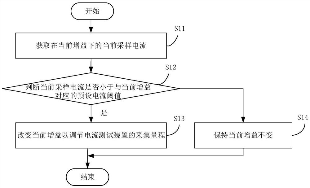
The invention discloses a current testing device which comprises a sampling module, a gain adjusting module and an upper computer. The sampling module is used for collecting differential signals at the two ends of the sampling resistor and feeding back the differential signals to the gain adjusting module, and the gain adjusting module is used for determining sampling current according to the differential signals and feeding back the sampling current to the upper computer. The upper computer adjusts the gain of the gain adjusting module according to the sampling current so as to change the acquisition range of the current testing device. According to the current testing device disclosed by the invention, the sampling current is determined according to the differential signals at the two ends of the sampling resistor, and the gain is adjusted according to the sampling current, so that the acquisition range of the current testing device is changed, and meanwhile, the precision of the current testing device can be adjusted, so that the measurement precision corresponds to the acquisition range; under the condition that the current testing device is not replaced, accurate measurement of currents of different magnitudes can be ensured. The invention further discloses a current testing method and electronic equipment.

Description

technical field [0001] The present application relates to the technical field of current testing, in particular to a current testing device, a current testing method and electronic equipment. Background technique [0002] In the related art, for the same current testing device, its range is usually fixed, and the range cannot be changed according to the size of the test current, and the test accuracy of the current test device is also fixed, and the test accuracy cannot be adjusted according to the size of the test current. transformation. When the fluctuation range of the sampling current is large, in order to ensure that the currents of different magnitudes can be accurately measured, it is necessary to replace the current testing devices with different ranges, and the testing process is relatively cumbersome. Contents of the invention [0003] In view of this, an embodiment of the present application provides a current test device, the current test device includes a sa...

Claims


Application Information

Patent Timeline
Patent Type & Authority Applications(China)
IPC IPC(8): G01R19/00G01R15/14
CPCG01R19/0092G01R15/14
Inventor 王成刚
Owner GUANGZHOU XIAOPENG MOTORS TECH CO LTD
Learn More