Live broadcast control method and device
A control method and data technology, applied in the direction of image communication, selective content distribution, electrical components, etc., can solve the problems of limited information seen, cumbersome switching of the sender repeatedly, and inability to play from multiple perspectives, so as to achieve good compatibility, Achieve convenience and enhance the effect of live broadcast function
Pending Publication Date: 2021-05-28
VISIONVERA INFORMATION TECH CO LTD
7 Cites 2 Cited by
AI-Extracted Technical Summary
Problems solved by technology
The two need to switch back and forth, only one can be selected, and multi-view playback is not possible
For the receiver, the information seen is limited, and for the sender, it is cumbersome to switch repeatedly
[0004] Therefore, it is necessary to solve the problem of how to make full use of the hardware resources of mobile devices to simultaneously play multiple video im...
Method used
The structural design of the Internet of View completely eradicates the network security problems that plague the Internet through the individual licensing system for each service, complete isolation of equipment and user data, etc., and generally does not require anti-virus programs and firewalls, eliminating hackers and Virus attacks, providing users with a structured worry-free security network.
The ultra-high-speed memory technology of unified video platform adopts the most advanced real-time operating system in order to adapt to the media content of super-large capacity and super-large flow, and the program information in the server instruction is mapped to concrete hard disk space, and the media content is no longer After passing through the server, it is sent directly to the user terminal in an instant, and the user generally waits for less than 0.2 seconds. The optimized sector distribution greatly reduces the mechanical movement of the hard disk head seeking. The resource consumption is only 20% of the IP Internet of the same level, but the concurrent traffic generated is 3 times larger than that of the traditional hard disk array, and the overall efficiency is increased by more than 10 times.
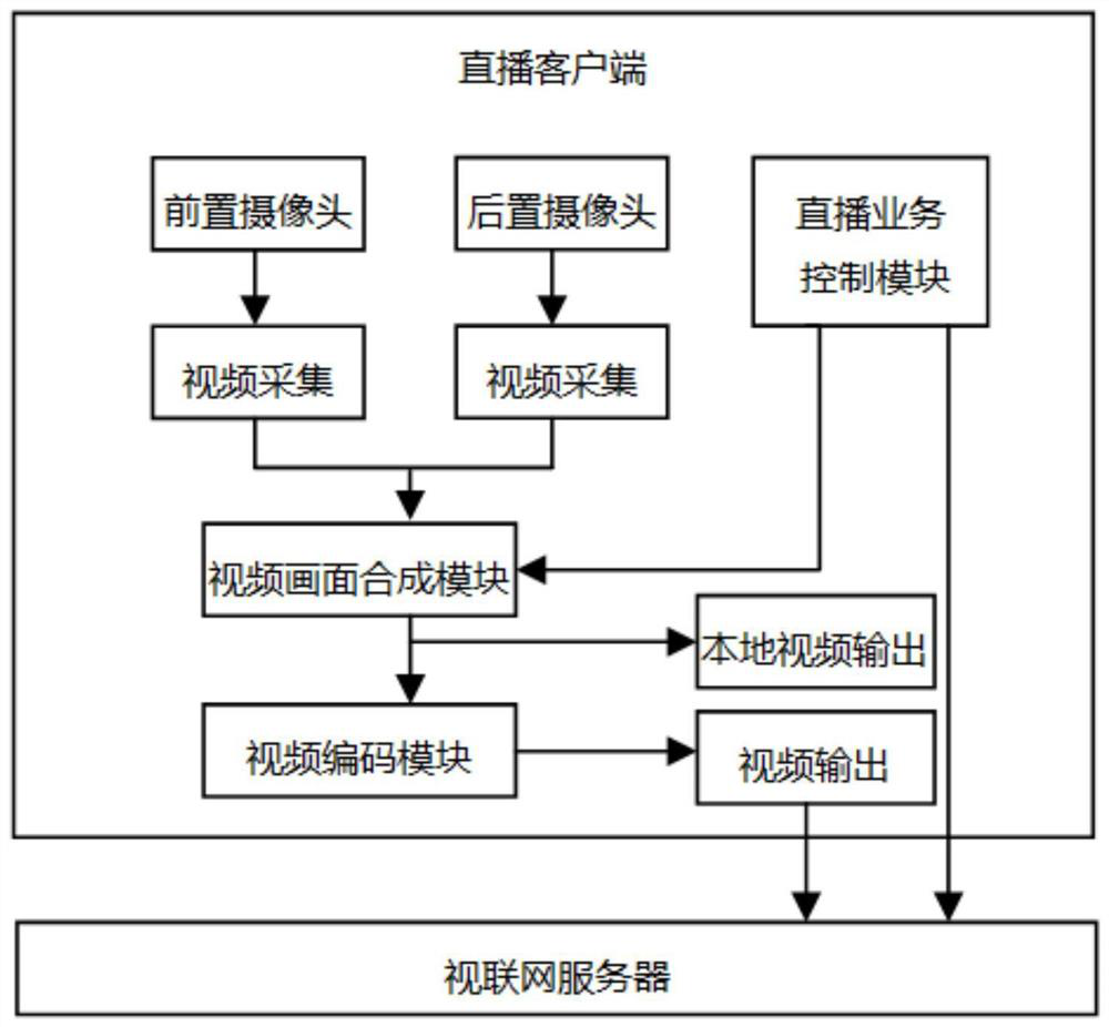
[0048] In order to solve the problem of how to make full use of the hardware resources of the mobile device and play multiple video images simultaneously from multiple perspectives. As shown in Figure 1, the embodiment of the present invention is applied to the live broadcast service in the video network ...
Abstract
The embodiment of the invention provides a live broadcast control method and device applied to a live broadcast client, the live broadcast client is in communication connection with a Video to Video Network server, and the method comprises the following steps: starting a plurality of cameras in a mobile device; acquiring multi-channel video data acquired by the plurality of cameras respectively; synthesizing the multi-channel video data to obtain target video data; encoding the target video data to obtain encoded data; and sending the encoded data to the Video to Video Network server so as to send the encoded data to an on-demand client through the Video to Video Network server. According to the invention, two paths of video pictures at different visual angles are collected at the same time, and the two paths of video pictures are synthesized in the same picture, so that the live broadcast function of the live broadcast client is greatly enhanced, a viewer can see two paths of pictures before and after a live broadcast party at the same time, different contents are played respectively, a receiver obtains more visual information, and understanding of broadcast content of the live broadcast party is facilitated.
Application Domain
Selective content distribution
Technology Topic
Real-time computingReceiver +4
Image
Examples
- Experimental program(1)
Example Embodiment
[0047]In order to make the above objects, features, and advantages of the present invention, the present invention will be further described in detail below with reference to the accompanying drawings and specific embodiments. Obviously, the described embodiments are all embodiments of the invention, not all of the embodiments. Based on the embodiments of the present invention, those of ordinary skill in the art will belong to the scope of the present invention without all other embodiments obtained without creative labor.
[0048]In order to solve how to make full use of hardware resources for mobile devices, multi-view simultaneous playback of multiple video screens simultaneously. Such asfigure 1 As shown, the embodiment of the present invention applies a live broadcast service in a video conference system implemented on a live broadcast client, started by the live broadcast service control module, at the beginning of the live broadcast, and initialize and open the front camera and the rear camera pair Two channels are collected, and the video screen is synthesized by setting the video screen in accordance with the setting of the live service control module, thereby moving the screen of the front and rear camera on the same screen to form a size screen or the left and right screen. The synthetic screen is output to the local video output for direct display on the live broadcast client, and the other screen is output to the video network server after video encoding, so that the Internet server can be distributed to other on-demand clients. By simultaneously acquiring two video screens in different perspectives, then two video screens are synthesized in the same screen, allowing both two-way screen to simultaneously display the two-way screen when streaming on the mobile device, thereby implementing a multi-view angle. Moreover, by synthesizing the two video pictures in the same screen, the video coding can be made to solve the multi-channel video acquisition synchronization problem, making the system easier. This approach can greatly improve the practicality, availability of mobile tablet, providing very powerful support in a variety of tasks such as on-site interview, learning and training, making live broadcast functions.
[0049]Among them, the video conferencing system: The video conferencing system is based on the high-definition video transmission based on the video network. Through the corresponding management software and client, the real-time high-definition conference system constructed, supports multiple dedicated terminals, mobile terminals Into. The main functions include: forming a conference, video call, publication, watching live, etc., related applications include: conference control, conference mobile, conference dispatch server, conference management web background, etc. The hardware terminals supported include: PC, mobile devices, and viewing tablets, etc.
[0050]Conference Control: Video Conference Scheduling System Client, the client software running on the PC platform for conference reservations, conference process management, control, start-stop meetings, switch spokespersons, split screen mode, etc. The front end of the system mainly operates modules, fully controlling the entire process of the meeting.
[0051]Meeting Mobile: Visual Network Mobile Conference Terminal, is a conference control end that streamlined in the mobile platform, the hardware platform is usually a flat panel (such as the Android of the PAD) or Android phones, etc., can be connected via wireless IP network connection To the dedicated network conferencing system management, meeting control and participation in conference operations are also available, and there is also functions such as live, video telephony.
[0052]Live broadcast: It is a feature of the Vision Conference System. The Vision Conference System can contain multiple types of terminals, including multi-channel high-definition dedicated terminals independently developed from the Internet, including mobile terminals, etc., live broadcast functions are any Terminal, collect local audio video data through the camera and push it to the video network, any other number of terminals, can choose to watch live audio and video of this terminal.
[0053]The embodiment of the present invention will be specifically described below:
[0054]referencefigure 2 A flow chart showing a live broadcast control method provided by the embodiment of the present invention, the live broadcast client communicates with a video web server, the method specifically, can include the following steps:
[0055]Step 201, start multiple cameras in the mobile device;
[0056]It should be noted that the mobile device can include various mobile terminals, such as mobile phones, tablets, PDAs, and the like. The operating system of the mobile device can include Android (Android), IOS, Windows Phone, Windows, etc., usually support operation of various applications.
[0057]The live broadcast client is a terminal running on the mobile device. In the embodiment of the present invention, the live broadcast client can initiate a plurality of cameras in the mobile device to collect audio and video through multiple cameras in mobile devices. data.
[0058]Specifically, the mobile device can include a front camera and a rear camera, and the live broadcast client can initiate a front camera and a rear camera in the mobile device.
[0059]Step 202, acquire multiple video data collected by the plurality of cameras;
[0060]Multiple cameras in mobile devices can collected video data from different perspectives, for example, the front camera can be collected video data from the front square front view of the front camera, and the rear camera can be collected from the front view of the back camera. data.
[0061]In an embodiment of the present invention, the live broadcast client can acquire multiple video data collected separately from multiple cameras in the mobile device, i.e., live broadcast clients can acquire video data collected from different perspectives.
[0062]Step 203, the synthesis of the multi-channel video data obtains the target video data;
[0063]In order to solve the problem of the acquired multi-channel video data, there is no synchronization, in the embodiment of the present invention, after acquiring multiple video data collected by multiple cameras, it is not directly output, but the first core synthesis Road video data gets target video data.
[0064]Specifically, the multi-channel video data can be scaled, superimposed, and superimposed in a particular form of a screen, for example, forming a specific form of a screen, for example, forming a size screen overlay or left and right picture. A picture in the form of a form. The preset synthetic parameters can be parameters in predetermined synthetic format predetermined.
[0065]Step 204, encoding the target video data to obtain encoded data;
[0066]In the embodiment of the present invention, after the synthesis multi-channel video data obtains the target video data, the target video data can be encoded to obtain encoded data.
[0067]Specifically, the coded data can be encoded based on the video compression protocol (such as the H.264 protocol) to facilitate transfer encoded data to the video server, and used for other on-demand clients to obtain encoded data in the video network server. Watch live broadcast.
[0068]Step 205 transmits the encoded data to the connected server to send the encoded data to the on-demand client via the connected network server.
[0069]In an embodiment of the present invention, encoded data can be sent to the video server to send encoded data to the on-demand client via the web server, so that the on-demand client can get the encoded data to watch live broadcast. Among them, the on-demand client can refer to the live broadcast of the live broadcast of the live broadcast client to the live broadcast client.
[0070]In the specific implementation, the live broadcast client can communicate with the dependent web server based on the Ethernet protocol, so that the live broadcast client can transmit encoded data to the video server based on the Ethernet protocol. After receiving the encoded data, the connected server can transmit encoded data based on the dependent network protocol, and transmit the encoded data to the on-demand client based on the Ethernet protocol.
[0071]In a preferred embodiment of the invention, the plurality of cameras includes a front camera and a rear camera that may include the following steps:
[0072]Call the video acquisition interface provided by the mobile device; start the front camera and the rear camera in the mobile device via the video acquisition interface.
[0073]The mobile device can have a video capture interface that is used to provide a port for other applications to obtain the front camera of the mobile device and the video data acquired by the back camera.
[0074]In an embodiment of the present invention, when a live broadcast service is performed, the live broadcast client can call the video acquisition interface provided by the mobile device and initiate a front camera and the rear camera in the mobile device via a video capture interface.
[0075]Specifically, the live broadcast client can include a live broadcast service control module and a video acquisition module, and the live broadcast service control module starts the video acquisition module to call the video capture interface provided by the mobile device via the video acquisition module and start the mobile device through the video capture interface. Pre-camera and rear camera.
[0076]In a preferred embodiment of the invention, the step 203 can include the following steps:
[0077]The multi-channel video data is stored in a plurality of video buffers, respectively; multi-channel data data within the plurality of video buffers is synthesized according to a preset synthetic parameter.
[0078]In order to solve the problem of the acquisition of multiple video data, there is no synchronization, in the embodiment of the present invention, the corresponding video buffers can be assigned to each camera acquisition, so that after the video data acquired by each camera, The video data can be stored in the corresponding video buffer.
[0079]As an example, the mobile device can include a front camera and a rear camera, and the video data acquired by the front camera can be stored to the video buffer 1, and the video data collected by the rear camera is stored to the video buffer.
[0080]After the multi-channel data data is stored in a plurality of video buffers, multi-channel data data in the plurality of video buffers can be synthesized in the preset composite parameters. In the specific implementation, the live broadcast client may include a video image synthesis module, which can read multiple video data from the plurality of video buffers through the video image synthesis module, and then preset the plurality of video data read by the synthetic parameters. Get target video data.
[0081]In a preferred embodiment of the invention, the video data consists of a multi-frame picture image; the multi-channel data in the video buffer is synthesized by a multi-frame video data, including:
[0082]Each frame image of the multi-channel video data is read from the frequency buffer; each frame image of the multi-channel video data is synthesized according to the preset synthetic parameter to obtain the target video data.
[0083]In the embodiment of the present invention, the video data can be composed of a multi-frame picture image, and when the multi-channel video data is synthesized, the multi-channel video data is read from the frequency buffer, and then according to the preset synthesis Parameter synthesis of multiple video data for each frame image.
[0084]In a preferred embodiment of the invention, the preset synthetic parameters include one or more of the resolution, size, and layout styles.
[0085]Among them, the resolution can refer to the amount of information stored in the picture image, which is how many pixels in each inch screen image. The size can refer to the size of the picture image. The layout style can refer to the way the screen is arranged, for example, the size screen superimposed style, the left and right picture parallel, or the upper and lower screen side screen, the present invention is not limited.
[0086]In a preferred embodiment of the invention, it may also include step 203 after step 203:
[0087]The target video data is displayed on the display of the mobile device.
[0088]In the embodiment of the present invention, after the synthesis multi-channel video data obtains the target video data, the first way of the target video data can be directly outputted to the local display, thereby presenting the target video data on the display of the mobile device.
[0089]Specifically, since the video screen is displayed locally on the live client, it is not necessary to obtain data by the Internet server, so it can directly output a direct output of the target video data to the local display, thereby displaying the target on the display of the mobile device. Video data.
[0090]In a preferred embodiment of the invention, the step 204 can include steps as follows:
[0091]The target video data is read according to the preset frame rate, and the encoded data is encoded based on the H264 protocol.
[0092]In the embodiment of the present invention, after the synthesis multi-channel video data obtains the target video data, the target video data can be read according to the preset frame rate, and the encoding data is encoded based on the H264 protocol. Wherein, the preset frame rate can be a frequency of preset screen frames. The H264 protocol is the latest video coding format defined by the MPEG-4 standard, and the H264 video format is damaged, but it is preferable to reduce the storage volume and low-bandwidth image.
[0093]In the specific implementation, the live broadcast client can include a video stream encoding module, which can read the target video data according to the preset frame rate through the video stream encoding module, and encoded the encoded data based on the H264 protocol.
[0094]In order to enable those skilled in the art to better understand the above steps, the following combinationimage 3 The embodiment of the present invention is exemplarily described, but it should be understood that the embodiment of the present invention is not limited thereto.
[0095]Specifically, the video acquisition module can be activated by the live broadcast service control module, and the video acquisition module is responsible for connecting the collection of each camera for video.image 3 In connection with the capture of the camera 1 and the camera 2 for video acquisition. It should be noted that the live broadcast service control module can also start the audio acquisition module of the mobile device, collecting the audio data through the audio acquisition module, and then integrating all the audio data and video data can be obtained.
[0096]After obtaining the video data acquired by the camera, the video data acquired by the camera 1 can be stored in the camera video acquisition buffer 1, and the video data acquired by the camera 2 is stored in the camera video acquisition buffer 2. Further, the latest image data is read from the two buffers, respectively, according to the specified resolution, size, and superimposed, and superimpose, the synthesis of the two video is separately read from the two buffers, the size, and the synthesis is superimposed. Parallel form. The synthetic video is directly output to the local video display. The synthetic video is further read by the video stream coding module, performs H264 encoding according to the set frame rate, and transmits the encoded data to the via the video V2V interface. The networker server is forwarded by the video network to other on-demand clients.
[0097]It should be noted that for method embodiments, for the sake of illustration, it will be specifically described as a series of operations, but those skilled in the art will be understood that the embodiments of the present invention are not limited by the described action sequence, because In accordance with an embodiment of the present invention, some steps can be carried out in other orders or simultaneously. Second, those skilled in the art should also be known that the embodiments described in the specification are preferred embodiments, and the actions involved are not necessarily necessary.
[0098]referenceFigure 4 The structural block diagram of a device provided by the embodiment of the present invention is shown, and the live broadcast client is used, the live broadcast client communicates with a video web server, and the apparatus can include a module:
[0099]The camera start module 401 is used to initiate multiple cameras in the mobile device;
[0100]The video data acquisition module 402 is configured to obtain multiple video data collected by the plurality of cameras;
[0101]Video data synthesis module 403 is used to synthesize the multi-channel video data to obtain target video data;
[0102]Video data encoding module 404 is configured to encode the target video data;
[0103]The encoded data transmitting module 405 is configured to transmit the encoded data to the connected server to transmit the encoded data to the on-demand client by the connected network server.
[0104]In a preferred embodiment of the invention, the plurality of cameras include a front camera and a rear camera, the camera start module 401, including:
[0105]Video acquisition interface calls submodules for calling the video capture interface provided by the mobile device;
[0106]The camera boot the submodule for initiating the front camera and the rear camera in the mobile device via the video acquisition interface.
[0107]In a preferred embodiment of the invention, the video data synthesis module 403 includes:
[0108]The video data storage submodule is configured to store the multi-channel video data into a plurality of video buffers, respectively;
[0109]The video data synthesis sub-module is configured to synthesize multiple video data in the plurality of video buffers to obtain target video data in accordance with preset synthetic parameters.
[0110]In a preferred embodiment of the invention, the video data consists of a multi-frame picture image; the video data synthesizing sub-module, including:
[0111]The picture image reading unit is configured to read each frame image of the multi-channel video data from the plurality of frequency buffers, respectively;
[0112]The picture image synthesis unit is configured to synthesize each frame image of the multi-channel video data in accordance with a preset synthetic parameter to obtain target video data.
[0113]In a preferred embodiment of the invention, the preset synthetic parameters include one or more of the resolution, size, and layout styles.
[0114]In a preferred embodiment of the invention, further comprising:
[0115]The video data display module is configured to display the target video data on the display of the mobile device.
[0116]In a preferred embodiment of the invention, the video data encoding module 404 includes:
[0117]The video data encoding submodule is configured to read the target video data in accordance with the preset frame rate, and encoded the encoded data based on the H264 protocol.
[0118]For device embodiments, since it is substantially similar to the method embodiment, the relatively simple, the partial description of the method embodiment will be described.
[0119]The embodiment of the present invention also provides an electronic device, including:
[0120]One or more processors;
[0121]It stores one or more machine readable media with instructions, and when executed by the one or more processors, the electronic device performs the step of performing the method of any of the embodiments of the present invention.
[0122]The embodiment of the present invention further provides a computer program that stores a computer program whose processor performs the process of any of the embodiments of the present invention.
[0123]According to the important milestone of network development, it is a real-time network that enables high-definition video real-time transmission, and many Internet applications are pushed to HD video, opposite.
[0124]The video network uses real-time HD video switching technology, you can use the services you need on a network platform, such as HD video conferencing, video surveillance, intelligent monitoring, emergency command, digital broadcasting, delay TV, online teaching, live broadcast , VOD on-demand, TV mail, personality recording (PVR), intranet (self-service) channel, intelligent video broadcast control, information release, etc. dozens of videos, voice, pictures, text, communication, data and other services all integrated in one System platform, high-definition quality video playback is achieved by television or computers.
[0125]Introduction to the embodiments of the present invention will be better understood by those skilled in the art:
[0126]Some techniques applied by the viewing network are as follows:
[0127]Network Technology (NetWork Technology)
[0128]The network technology innovation of the connected network has improved the traditional Ethernet (Ethernet) to facing the potential huge first video traffic on the network. Different from a pure network packet exchange (Circuit Switching) or network circuit swap (Circuit Switching), the video technology is used to meet the streaming requirements. The video technology has a flexible, simple and low price of group exchange, and has a quality and security guarantee of circuit exchange, achieving a full-network switching virtual circuit, and a seamless connection in the data format.
[0129]Switching Technology
[0130]According to the asynchronous and package exchange of Ethernet, the network is used, and the Ethernet defect is eliminated under full-compatible, and the all-NANT is seamlessly connected, and the only user terminal is directly loaded with the IP packet. User data does not require any format conversion within the entire network. The connected network is a higher-level form of Ethernet. It is a real-time exchange platform that enables the current Internet to unable to implement a large-scale high-definition video real-time transmission, and push many network video applications to HD and unify.
[0131]Server Technology (Server Technology)
[0132]The server technology on the connected network and the unified video platform is different from the traditional server. Its streaming media transmission is based on the connection-oriented, and its data processing power, communication time is independent, and a single network layer can contain a letter. Order and data transmission. For voice and video services, the complexity of the video and unified video platform streaming is much simpler than data processing, and the efficiency is more than 100 times higher than that of the traditional server.
[0133]Storage Technology (Storage Technology)
[0134]Ultra-high-speed reservoir technology of the unified video platform adapts the most advanced real-time operating system in order to adapt to large capacity and large traffic media content, map program information in the server instruction to the specific hard disk space, the media content is no longer passed by the server, The instant delivery reaches the user terminal, and the user waits for a general time less than 0.2 seconds. The optimized sector distribution greatly reduces the mechanical movement of the hard disk magnetic head finding, and resource consumption only accounts for 20% of the same grade IP Internet, but generates three-fold concurrent traffic greater than conventional hard disk arrays, and the comprehensive efficiency is more than 10 times.
[0135]Network Security Technology (NetWork Security Technology)
[0136]The structural design of the viewing network is completely isolated by each service separate license system, and the device is completely isolated from the structure. In addition to the network security issues that plague the Internet, there is generally no need for anti-virus programs, firewalls, and eliminate hackers and viruses. To provide users with structural worry-free security networks.
[0137]Service INNOVATION Technology (Service Innovation Technology) (SERVICE INNOVATION TECHNOLOGY)
[0138]The unified video platform combines business and transmission, whether a single user, private network user is still a network, but it is all automatically connected. User terminals, set top boxes or PCs are directly connected to the unified video platform to get a variety of multimedia video services. The Unified Video Platform uses the "recipe" template to replace the traditional complex application programming, you can use very little code to implement complex applications, implement "unlimited amount" new business innovation.
[0139]The network of the connected network is as follows:
[0140]According to a centralized network structure, the network can be a tree, star network, a cyclic mesh, etc., but on this basis, a centralized control node is required to control the entire network.
[0141]Such asFigure 5 As shown, the connected network is divided into two parts: access network and metropolitan area.
[0142]The device of the access network can be divided into three categories: node servers, access switches, terminals (including various set top boxes, codes, memory, etc.). The node server is connected to the access switch, and the access switch can be connected to a plurality of terminals and can connect the Ethernet.
[0143]Where the node server is a node that serves a centralized control function in the access network to control access switches and terminals. The node server can be connected directly to the access switch or directly connected to the terminal.
[0144]Similarly, the equipment of the metro network can also be divided into three categories: metropolitan server, node switches, node servers. The metropolitan server is connected to the node switch, and the node switch can be connected to multiple node servers.
[0145]Among them, the node server is the node server of the access network, that is, the node server belongs to the access network portion and belongs to the Metropolitan area network section.
[0146]Metropolitan server is a node that serves as a centralized control function in the Metro network, which controls node switches and node servers. The metropolitan server can directly connect to the node switch, or directly connect the node server.
[0147]It can be seen that the entire dedicated network is a network structure of a hierarchically centralized control, and the network controlled under the node server and the metropolitan server can be a tree, star, annular, and other structures.
[0148]The image is called, the access network portion can form a unified video platform (part of the virtual coil), and multiple unified video platforms can be constructed; each unified video platform can be interconnected through the metropolitan area and wide-area video network interconnection.
[0149]Visual network equipment classification
[0150]1.1 Equipment in the viewing network of the embodiment of the present invention can primarily be classified into three classes: servers, switches (including Ethernet Cooperation Gateways), terminals (including various set top boxes, codes, memory, etc.). The entire view can be divided into metropolitan area network (or national network, global network, etc.) and access network.
[0151]1.2 The equipment in which the access network portion can be divided into three categories: node servers, access switches (including Ethernet Corrive Gateways), terminals (including various set top boxes, codes, memory, etc.).
[0152]The specific hardware structure of each access network device is:
[0153]Node server:
[0154]Such asFigure 6 As shown, there is mainly a network interface module 201, a switching engine module 202, a CPU module 203, a disk array module 204;
[0155]The network interface module 201, the CPU module 203, the disk array module 204 comes in into the switching engine module 202; the switching engine module 202 comes into the operation of the address table 205, thereby obtaining the guidance information of the package; The guidance information of the package stores the package into the queue of the corresponding package buffer 206; if the queue of the package buffer 206 is close, then discard; the switch engine module 202 polls all package buffer queues, if the following conditions are met: 1) This port is sent to the cache; 2) The queue package counter is greater than zero. The disk array module 204 mainly implements the control of the hard disk, including initialization, reading and writing, etc. of the hard disk; the CPU module 203 is mainly responsible for processing between the access switch, the terminal (not shown), and the address table 205. (Including the downlink protocol package address table, the uplink protocol package address table, packet address table), and the configuration of the disk array module 204.
[0156]Access switch:
[0157]Such asFigure 7 As shown, there is mainly a network interface module (downlink network interface module 301, uplink network interface module 302), switched engine module 303, and CPU module 304;
[0158]Among them, the packet (uplink data) enters the package (uplink data) in the downlink network interface module 301; the package detection module 305 detects the destination address (DA), the source address (SA), the packet type, and the package length meet the requirements, if In line with the corresponding stream identifier (stream-id), and enter the switching engine module 303, otherwise discard; the package (downlink data) entered by the uplink network interface module 302 into the switching engine module 303; CPU module 304 incoming packet Entering the switching engine module 303; the switching engine module 303 comes to the operation of the address table 306 to obtain the operation of the address table 306, thereby obtaining the guided information of the package; if the package to enter the switching engine module 303 is the downlink network interface to the upper network interface, then combine The stream identifier (stream-id) stores the package into the queue of the corresponding package buffer 307; if the queue of the package buffer 307 is close, discard; if the package of the switching engine module 303 is not a downlink network interface If the network interface is removed, the packet is stored in the queue of the corresponding package buffer 307 according to the guidance information of the package; if the queue of the package buffer 307 is close, it is discarded.
[0159]The switch engine module 303 polls all package buryer queues, which can include two situations:
[0160]If the queue is going to the uplink network interface, the following conditions are met: 1) This port is sent cache is not full; 2) The queue package counter is greater than zero; 3) Get the token generated by the code rate control module ;
[0161]If the queue is not going to the upper network interface to the upper network interface, the following conditions are met: 1) The port is not full; 2) The queue package counter is greater than zero.
[0162]The code rate control module 308 is configured by the CPU module 304 that generates a token to all downlink network interfaces to the upstream network interface in the programmable interval to control the code rate of upstream forwarding.
[0163]The CPU module 304 is primarily responsible for processing between the protocols between the node servers, the configuration of the address table 306, and the configuration of the code rate control module 308.
[0164]Ethernet Cooperation Gateway :
[0165]Such asFigure 8 As shown, it mainly includes a network interface module (downlink network interface module 401, the uplink network interface module 402), the switching engine module 403, the CPU module 404, the package detection module 405, the code rate control module 408, address table 406, package buffer 407 And Mac Add Module 409, MAC Delete Module 410.
[0166]Among them, the packet entry block detection module 405 incorporated by the downlink network interface module 401; the package detection module 405 detects the Ethernet MAC DA of the packet, Ethernet Mac SA, Ethernet Length Length Type, View Network Location Address DA, Visual Network The source address SA, the video package type, and the package length meet the requirements, if the corresponding stream identifier (stream-id) is assigned; then, minus Mac DA, Mac Sa, Length or Frame Type is subtracted by the Mac deletion module 410 (2byte) and enter the corresponding reception cache, otherwise discard;
[0167]The downstream network interface module 401 detects the transmission cache of the port. If there is a packet, according to the connected network of the packet, the Ethernet MAC DA of the corresponding terminal is obtained according to the view of the package, add the terminal Ethernet MAC DA, Ethernet Corrive Gateway MACSA, Ethernet Length or Frame Type, and send it.
[0168]The function of other modules in the Ethernet Corresponding Gateway is similar to the access switch.
[0169]terminal:
[0170]It mainly includes a network interface module, a business processing module, and a CPU module; for example, the set top box mainly includes a network interface module, an optic code decoding engine module, a CPU module; the encoder mainly includes a network interface module, an optical audio encoding engine module, a CPU module; memory It mainly includes network interface modules, CPU modules, and disk array modules.
[0171]1.3 The equipment of the metro network can be mainly divided into 2 categories: node server, node switch, metropolitan server. The node switch mainly includes a network interface module, a switched engine module, and a CPU module; the metropolitan server mainly includes a network interface module, a switching engine module, and a CPU module.
[0172]2. Definition of the video package
[0173]2.1 Access network packet definition
[0174]The data packet of the access network mainly includes the following sections: destination address (DA), source address (SA), reserved byte, PayLoad (PDU), CRC.
[0175]As shown in the table below, the data packets of the access network mainly include the following parts:
[0176] DA SA RESERVED PayLoad CRC
[0177]among them:
[0178]The destination address (DA) consists of 8 bytes, the first byte represents the type of packet (such as various protocol packages, multicast packets, unicast packets, etc.), with up to 256 possible, The second byte to the sixth byte is the metropolitan area network address, seventh, and the eighth byte are the access network address;
[0179]The source address (SA) is also composed of 8 bytes, the definition is the same as the destination address (DA);
[0180]The reserved byte consists of 2 bytes;
[0181]The PayLoad section has different lengths according to the type of different datagrams. If it is a 64 byte, if it is a single-demand data package is 32 + 1024 = 1056 bytes, of course, is not limited to The above two types;
[0182]The CRC has 4 bytes, which computes the standard Ethernet CRC algorithm.
[0183]2.2 Member Network Packet Definition
[0184]The topology of the metropolitan area is a diagram, there may be two or more types of connections, namely, node switches and node servers, node switches, and node switches, node switches and node servers. A connection. However, the metropolitan area network address of the metro network device is unique. In order to accurately describe the connection between the metropolitan area network, the parameter is introduced in the embodiment of the present invention: tag, to uniquely describe a metro network device.
[0185]The definition of the label in this specification is similar to the label of MPLS (Multi-Protocol Label Switch, Multi-Protocol Tag Exchange), and there is two connections between the device A and the device B, then the data package is from the device A to the device B. 2 labels, packets from device B to device A also have 2 labels. The label is inserted into the label, the label, assuming that the packet enters the device A of the label (into the label) is 0x0000, the label (outlay) of the data package is off the device A may become 0x0001. The netflow process of the Metropolitan area network is the networking process under central control, which means that the address assignment of the metro network is dominated by the domain server, the node switch, and the node server are executed, this is The label allocation with MPLs is different, and the MPLS label allocation is the result of the switch, the server negotiates each other.
[0186]As shown in the table below, the data packets of the Metropolitan area mainly include the following parts:
[0187] DA SA RESERVED label PayLoad CRC
[0188]That is, the destination address (DA), source address (SA), reserved byte (RESERVED), label, PayLoad (PDU), CRC. Among them, the label format can refer to the following definition: The tag is 32bit, where the height 16bit is reserved, with a low 16bit, its location is between the packet's reserved byte and the PayLOAD.
[0189]Each of the embodiments in this specification describes a manner described. Each of the various embodiments are described in relation to other embodiments, and each of the embodiments can be found in each other.
[0190]Those skilled in the art will appreciate that embodiments of the embodiments of the present invention can be provided as a method, apparatus, or computer program product. Thus, embodiments of the present invention may employ a full hardware embodiment, a full software embodiment, or a form of an embodiment in combination of software and hardware. Moreover, the embodiment of the present invention may employ a computer program product in one or more computers (including, but not limited to, disk storage, CD-ROM, optical memory, etc.) implemented in one or more computers.
[0191]Embodiments of the present invention are described with reference to a method, a terminal device (system), and a flowchart and / or block diagram of a computer program product, in accordance with an embodiment of the present invention. It should be understood that each of the flowcharts and / or blocks in the flowchart and / or block diagram can be implemented by a computer program command, and a combination of flow and / or box in the flowchart and / or block diagram. These computer program instructions can be provided to generic computers, dedicated computers, embedded processes, or other programmable data processing terminal devices to generate a machine such that instructions executed by the processor of the terminal device through a computer or other programmable data processing Produce for implementationFigure oneProcess or multiple processes and / or boxesFigure oneApparatus specified in multiple boxes or multiple boxes.
[0192]These computer program instructions can also be stored in a computer readable memory capable of booting a computer or other programmable data processing terminal device in a particular manner such that instructions stored in the computer readable memory generates a manufacturing article of instruction devices. The instruction device is implemented in the processFigure oneProcess or multiple processes and / or boxesFigure oneThe function specified in the box or multiple boxes.
[0193]These computer program instructions can also be loaded onto a computer or other programmable data processing terminal such that a series of operation steps are performed on a computer or other programmable terminal device to generate a computer implemented process, thereby in a computer or other programmable terminal device. The instructions executed are provided for implementationFigure oneProcess or multiple processes and / or boxesFigure oneThe steps of the function specified in multiple boxes or multiple boxes.
[0194]While the preferred embodiments of the embodiments of the invention have been described, other modifications and modifications can be made to other embodiments of the present invention have been described in terms of the basic creative concepts. Therefore, the appended claims are intended to be construed as including preferred embodiments and all changes and modifications falling in the scope of the embodiments of the present invention.
[0195]Finally, it will also be noted that in this article, relationship terms such as the first and second, etc. are only used to distinguish an entity or operation with another entity or an operational area, and not necessarily or imply these entities. Or there is any such practical relationship or order between operations. Moreover, the term "comprising", "inclusive" or any other variable is intended to cover non-exclusive contained comprise a series of elements, methods, items, or terminal devices not only include those elements, but also include no clear columns. Other elements, or elements that include such processes, methods, items, or terminal devices. In the absence of more restrictions, the elements defined by the statement "include ...", and there is no other same elements in the process, method, item, or terminal device including the element.
[0196]The foregoing live control method and a live broadcast control device provided in the present invention have been described in detail, and the specific examples are used herein to explain the principles and embodiments of the present invention, and the above embodiments are intended to help understand The method of the present invention and its core thinking; at the same time, in the foreman, according to the forensic, according to the thoughts of the present invention, there will be changes in the specific embodiments and applications, in summary, the contents of this specification should not It is understood that the limitation of the invention.
PUM


Description & Claims & Application Information
We can also present the details of the Description, Claims and Application information to help users get a comprehensive understanding of the technical details of the patent, such as background art, summary of invention, brief description of drawings, description of embodiments, and other original content. On the other hand, users can also determine the specific scope of protection of the technology through the list of claims; as well as understand the changes in the life cycle of the technology with the presentation of the patent timeline. Login to view more.
Similar technology patents
Automatic multi-direction material carrying, loading and unloading equipment
Owner:UNIV OF ELECTRONIC SCI & TECH OF CHINA
Method for manufacturing low-carbon and low-silicon steel
Owner:SGIS SONGSHAN CO LTD
Estimation method for endurance mileage of electric vehicle
Owner:ANHUI NORMAL UNIV
System and method for accurate measuring transmission effect of P2P stream media netwrok for video / audio programs
Owner:WANGSHITIANYUAN IT TECH
Locking method, unlocking method and device thereof, network equipment and communication terminal
Owner:HUAWEI DEVICE (SHENZHEN) CO LTD