Installation method of adaptive windproof communication base station

A technology for communication base stations and installation methods, which can be applied to wind power generation, building types, wind turbines, etc., and can solve problems such as being easily broken by force, and communication base stations are loose and toppled, and achieve the effects of reducing wind resistance and height

Active Publication Date: 2021-06-01
中国通信建设北京工程局有限公司
View PDF6 Cites 0 Cited by
  • Summary
  • Abstract
  • Description
  • Claims
  • Application Information

AI Technical Summary

Problems solved by technology

[0003] The invention provides an installation method of an adaptive windproof communication base station, which can solve the problems that the communication base station in the prior art is easy to be loose and toppled, and is easy to be broken when encountering a strong wind

Method used


Image

  • Installation method of adaptive windproof communication base station
  • Installation method of adaptive windproof communication base station
  • Installation method of adaptive windproof communication base station

Examples


Embodiment 1

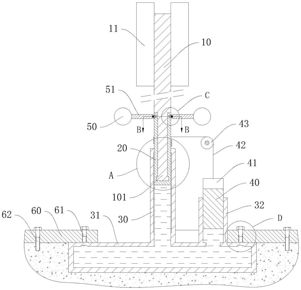
[0051] Such as Figure 1 to Figure 4 As shown, an installation method of an adaptive windproof communication base station provided by an embodiment of the present invention, the communication base station includes a transceiver device 11, and also includes a supporting device, a fixing device and a weight:

[0052] The support device includes a base rod 10 and a support rod 101, the support rod 101 is coaxially fixed on the base rod 10, the support rod 101 is located below the base rod 10, and the transceiver device 11 is fixedly arranged on the base rod 10;

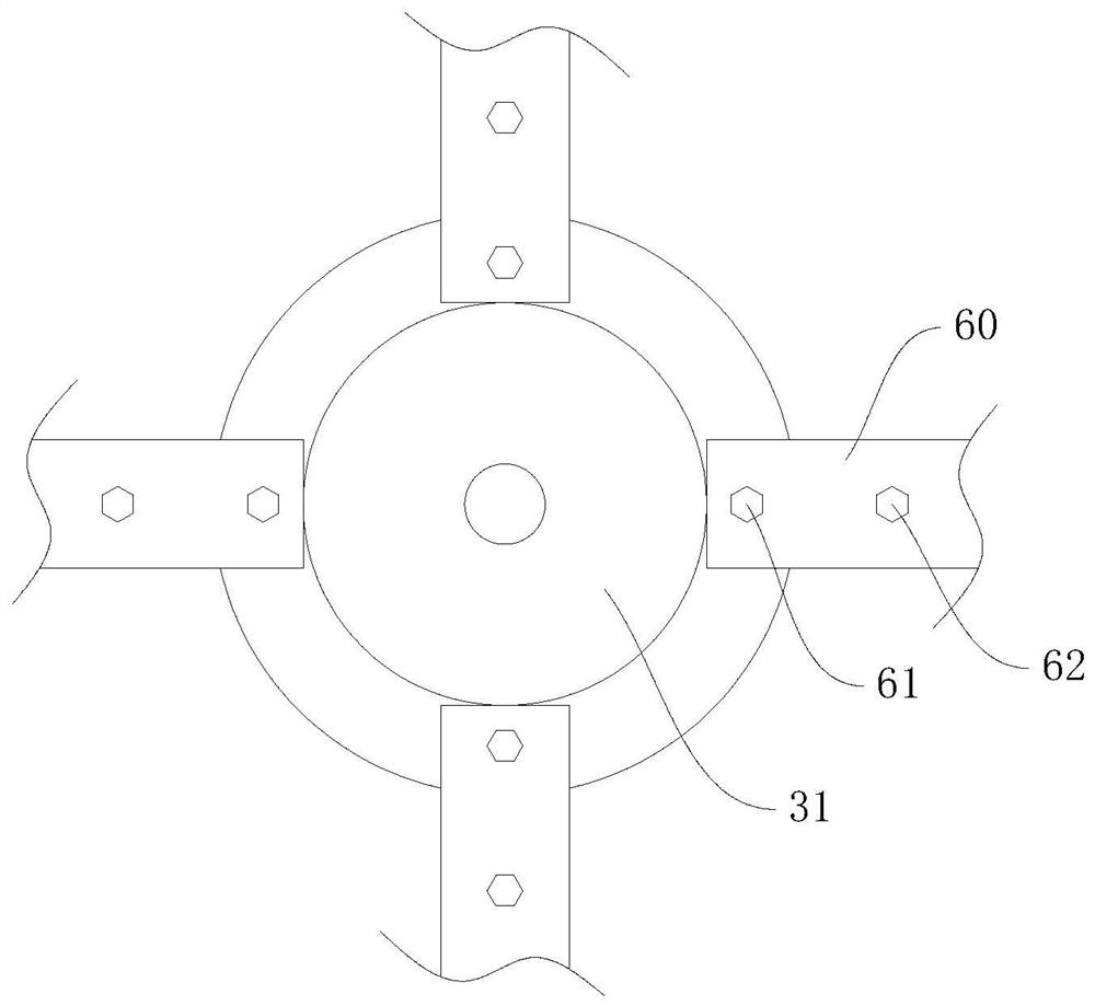
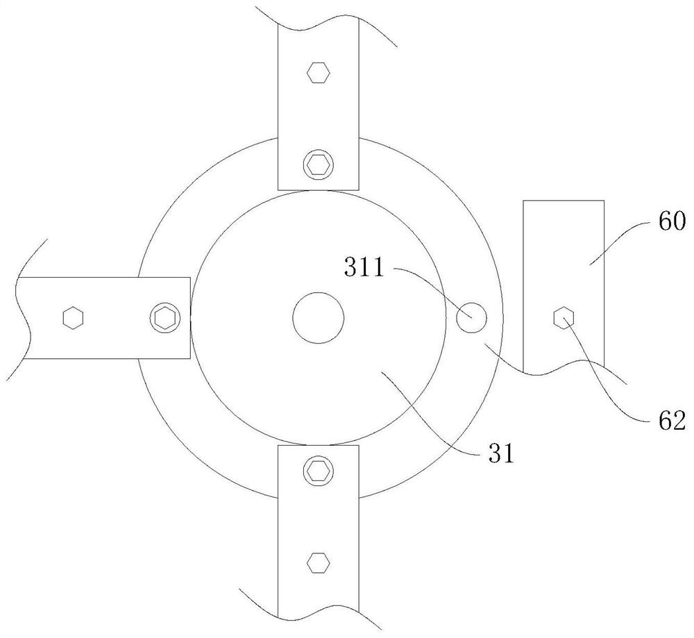
[0053] The fixing device comprises a longitudinal rod 30, a flange 31, a pressure plate 60, a compression bolt 61 and a fastening bolt 62, the longitudinal rod 30 is fixedly arranged on the flange 31, and the longitudinal rod 30 and the flange 31 are coaxially arranged , the longitudinal rod 30 and the flange 31 are both hollow structures, the longitudinal rod 30 penetrates into the flange 31, and the upper end of the lo...

Embodiment 2

[0071] In the first embodiment, since the support rod 101 remains at the top when the wind force is small or there is no wind, the hydraulic oil will be lost. When the hydraulic oil is lost, the weight 40 will move down, which will cause the cable 42 to be tight. The cable 42 is prone to wear or damage. In addition, after the hydraulic oil is lost, since the support rod 101 cannot move up, the cable 42 has no extra margin for the weight 40 to move down, resulting in a decrease in hydraulic oil pressure, which cannot be effectively maintained. The tightening bolt 61 and the tightening bolt 62 are clamped. Therefore, in this embodiment, the upper end of the weight 40 is fixedly provided with a telescopic part 41, and one end of the cable 42 is fixedly connected to the rotating sleeve 20, and the other end is fixedly connected to the telescopic part 41. The portion 41 expands and contracts when subjected to an external force. After the hydraulic oil is lost, the liquid level of t...

Embodiment 3

[0074] On the basis of Embodiment 1 or 2, when the wind force is small, the structural strength can meet the requirements, and there is no need to rotate the rotating sleeve 20. Frequent rotation of the rotating sleeve 20 will cause accelerated wear of the entire device, and when the wind is strong, the wind resistance is large. The load that the base bar 10 is subjected to becomes larger, and it is easy to cause damage to parts such as the base bar 10 or the support bar 101. In order to prevent the above problems, as Figure 7 to Figure 9 As shown, this embodiment also includes a first pawl 52, a second pawl 54, a first return spring 53 and a second return spring 55;

[0075] The connecting rod 51 is rotatably arranged on the rotating sleeve 20 along the circumferential direction of the rotating sleeve 20, and the rotating sleeve 20 is provided with a first ratchet groove matching with the first pawl 52 and a second ratchet groove matching with the second pawl 54. Two ratchet...


PUM


Abstract

The invention discloses an installation method of an adaptive windproof communication base station, and belongs to the field of communication equipment. The device comprises a transceiver, and further comprises a support device and a fixing device, wherein the support device comprises a base rod and a support rod; the support rod is coaxially fixed on the base rod; the fixing device comprises a longitudinal rod, a flange plate, a pressing bolt and a fastening bolt; the longitudinal rod is fixed on the flange plate; the longitudinal rod and the flange plate are both hollow structures; the support rod is slidably arranged in the longitudinal rod in a sealing manner; the longitudinal rod and the flange plate are filled with hydraulic oil; multiple elastic jacking parts are arranged at the upper end of the flange plate; the pressing plate is mounted on a foundation through the fastening bolt; one end of the pressing plate is pressed on the flange plate; and a thread hole is formed in the pressing plate. The device can keep a fastening state of the pressing bolt, so that the pressing bolt can always keep a pressing state to prevent deviation and looseness of the flange plate caused by looseness of the pressing bolt.

Description

technical field [0001] The invention relates to the field of communication equipment, in particular to an installation method of an adaptive windproof communication base station. Background technique [0002] At present, many communication base stations are generally fixedly installed on the roof of the building through brackets and other structures, which can increase the communication range and rationally use the space on the top floor. However, the existing roof base station poles are generally fixed by steel pipes plus supports and driven into the wall or floor slab with expansion screws. With the age of the building and the aging strength of the roof wall and concrete, there is a great potential safety hazard. Risk of water leakage and rain leakage, easy to damage the roof insulation layer, waterproof layer and other defects, and because the overall height of the entire bracket and communication equipment is high, the wind force at high altitude is strong, and the wind ...

Claims


Application Information

Patent Timeline
Patent Type & Authority Applications(China)
IPC IPC(8): E04H12/00E04H12/18E04H12/22F03D9/20F03D9/45
CPCE04H12/00E04H12/182E04H12/22E04H12/2269F03D9/20F03D9/45Y02B10/30
Inventor 不公告发明人
Owner 中国通信建设北京工程局有限公司
Why Eureka
Try Eureka