Installation method of self-adjusting communication equipment

A technology of communication equipment and installation method, which is applied in the direction of mechanical equipment, building types, screws, etc., can solve problems such as loosening and dumping, communication base stations cannot withstand harsh environments, etc., and achieve the effect of avoiding loosening

Inactive Publication Date: 2021-05-04
苗广传
View PDF0 Cites 2 Cited by
  • Summary
  • Abstract
  • Description
  • Claims
  • Application Information

AI Technical Summary

Problems solved by technology

[0003] The invention provides a method for installing self-adjusting communication equipment, which can solve the problem that the communication base station in the prior art cannot withstand the harsh environment and is easy to cause loosening and dumping

Method used


Image

  • Installation method of self-adjusting communication equipment
  • Installation method of self-adjusting communication equipment
  • Installation method of self-adjusting communication equipment

Examples


Embodiment 1

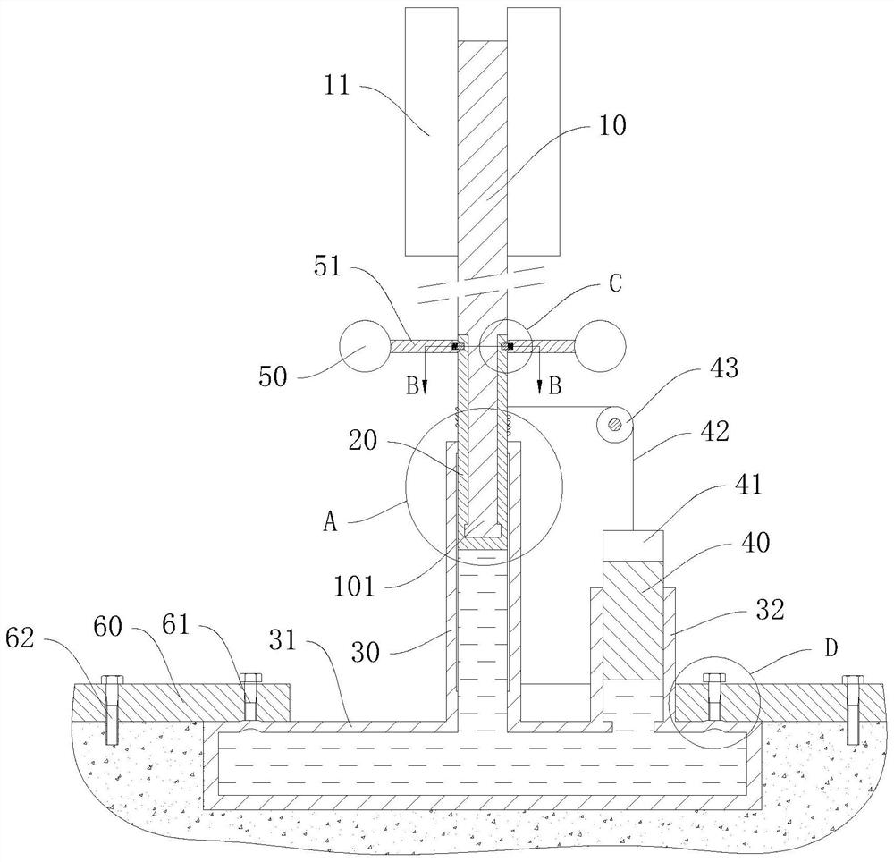
[0053] Such as Figure 1 to Figure 4 As shown, the embodiment of the present invention provides a self-adjusting communication device installation method, the communication device includes a transceiver device 11, and also includes:

[0054] The support device includes a base rod 10 and a support rod 101, the support rod 101 is coaxially fixed on the base rod 10, the support rod 101 is located below the base rod 10, and the transceiver device 11 is fixedly arranged on the base rod 10;

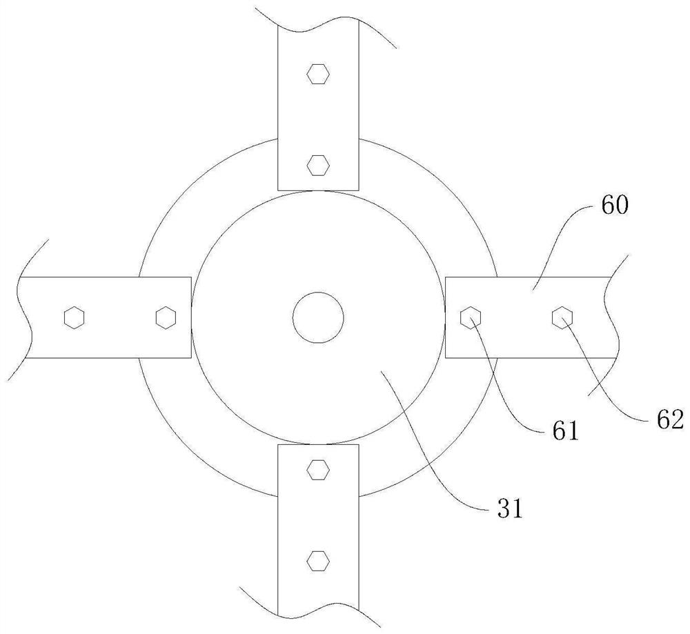
[0055] The fixing device comprises a longitudinal rod 30, a flange 31, a pressure plate 60, a compression bolt 61 and a fastening bolt 62, the longitudinal rod 30 is fixedly arranged on the flange 31, and the longitudinal rod 30 and the flange 31 are coaxially arranged , the longitudinal rod 30 and the flange 31 are both hollow structures, the longitudinal rod 30 penetrates into the flange 31, and the upper end of the longitudinal rod 30 is open; the support rod 101 is arranged in the longitudi...

Embodiment 2

[0067] In the first embodiment, due to the loosening of the bolts and / or the loss of hydraulic oil, the support rod 101 will move down, thereby causing the height of the transceiver device 11 to decrease, which does not meet the design requirements. Therefore, this embodiment also includes a weight 40, such as figure 1 As shown, the flange 31 is provided with an adjustment rod 32, the adjustment rod 32 is a hollow structure and penetrates into the flange 31, and the weight 40 is arranged in the adjustment rod 32 in a sealed and sliding manner up and down; the weight of the weight 40 is greater than The sum of the weights of the support rod 101 and the transceiver device 11 keeps the support rod 101 at the top. After the bolts are loosened and / or the hydraulic oil is lost, due to the heavy weight of the heavy hammer 40, the heavy hammer 40 is preferentially lowered to increase the pressure of the hydraulic oil, so that the pressing bolt 61 and the fastening bolt 62 are pressed t...

Embodiment 3

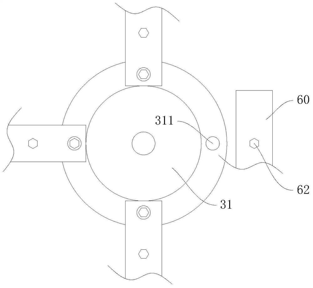
[0070] On the basis of embodiment one or two, such as Figure 6 As shown, since the communication base station is set high on the roof of the building, when the wind is strong, it is easy to cause excessive load on the base pole 10, resulting in equipment damage, fatigue of the installation structure, etc., and even the breakage of the base pole 10 affects communication. The embodiment also includes a rotating sleeve 20, a connecting rod 51, a wind cup 50, and a cable 42. The support rod 101 is rotatably arranged in the rotating sleeve 20. The lower end of the rotating sleeve 20 is closed and is dynamically and sealedly connected with the longitudinal rod 30. Because the transceiver device 11 and the base rod 10 have weight, and when the rotating sleeve 20 rotates, the support rod 101 remains relatively stationary to a certain extent; the rotating sleeve 20 is provided with an external thread, and the longitudinal rod 30 is provided with an internal thread matched with the exte...


PUM


Abstract

The invention discloses an installation method of self-adjusting communication equipment, and belongs to the field of communication equipment. The communication equipment comprises receiving and transmitting equipment, and further comprises a supporting device and a fixing device, wherein the supporting device comprises a base rod and a supporting rod; the fixing device comprises a longitudinal rod, a flange plate, pressing plates, pressing bolts and fastening bolts; the supporting rod is arranged in the longitudinal rod in a sealing and sliding mode; the longitudinal rod and the flange plate are filled with hydraulic oil, and a plurality of elastic jacking parts are arranged at the upper end of the flange plate; and the pressing plates are installed on a foundation through the fastening bolts. The installation method comprises the following steps that S1, the flange plate is placed in a foundation pit; S2, the pressing plates are uniformly arranged on the peripheral side of the flange plate in the circumferential direction; S3, the pressing plates are rotated, so that threaded holes in the pressing plates correspond to the elastic jacking parts on the flange plate; S4, the flange plate is filled with hydraulic oil; and S5, the supporting rod is installed in the longitudinal rod. According to the installation method, the fastening state of the pressing bolts can be kept, and the situation that the flange plate deviates and is loosened due to the fact that the pressing bolts are loosened is avoided.

Description

technical field [0001] The invention relates to the field of communication equipment, in particular to a method for installing self-adjusting communication equipment. Background technique [0002] At present, many communication base stations are generally fixedly installed on the roof of the building through brackets and other structures, which can increase the communication range and rationally use the space on the top floor. However, the existing roof base station poles are generally fixed by steel pipes plus supports and driven into the wall or floor slab with expansion screws. With the age of the building and the aging strength of the roof wall and concrete, there is a great potential safety hazard. Risk of water leakage and rain leakage, easy to damage the roof insulation layer, waterproof layer and other defects, and because the overall height of the entire bracket and communication equipment is high, the wind force at high altitude is strong, and the wind direction an...

Claims


Application Information

Patent Timeline
Patent Type & Authority Applications(China)
IPC IPC(8): E04H12/22F16B39/02
CPCE04H12/2269F16B39/02
Inventor 不公告发明人
Owner 苗广传
Why Eureka
Try Eureka