
Isolating switch contact finger pressure sensor, tester and method

A pressure sensor, isolating switch technology, applied in force/torque/work measuring instruments, instruments, measuring devices, etc., can solve problems such as poor operation, easy to fall off, measurement error, etc.

Pending Publication Date: 2021-06-01
ELECTRIC POWER RES INST OF EAST INNER MONGOLIA ELECTRIC POWER +1
View PDF13 Cites 0 Cited by
  • Summary
  • Abstract
  • Description
  • Claims
  • Application Information

AI Technical Summary

Problems solved by technology

[0002] At present, the pressure sensors are all 2 ~ 3cm cylindrical structure, but because the shape of the isolating switch is different, especially when measuring the clamping force between the dynamic and static contact rods of the scissor type isolating switch, because the contact surfaces of the contact rods are all point contact or line contact When measuring, the cylindrical pressure sensor is artificially placed on the contact surface, which is easy to fall off and difficult to operate, and it is artificially placed at the moment when the contact rod is closed. The center of the sensor is not necessarily at the center of the contact surface, which may easily cause measurement errors.

Method used


Image

  • Isolating switch contact finger pressure sensor, tester and method
  • Isolating switch contact finger pressure sensor, tester and method

Examples


Embodiment 1

[0020] Such as figure 1 as shown,

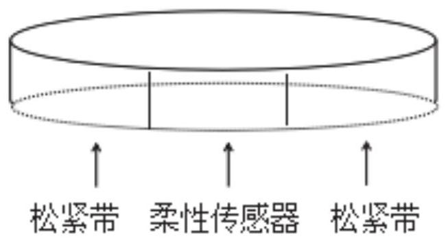
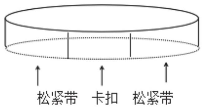
[0021] Such as figure 1 As shown, the present disclosure provides a contact finger pressure sensor of an isolating switch, including: a pressure sensor, a positioning structure connected to the pressure sensor; the positioning structure includes an elastic member and a clamping member, one end of the elastic member is connected to the housing, The other end is connected with the contact finger of the isolating switch to be tested; one end of the clamp is connected with the housing, and the other end is connected with the contact finger of the isolating switch to be tested.

[0022] Further, the elastic member includes several elastic bands, including at least two circumferential elastic bands and multiple radial elastic bands; the two circumferential elastic bands are respectively the first circumferential elastic band and the second circumferential elastic band, and the first circumferential elastic band The elastic band is installed on o...

Embodiment 2

[0028] The present disclosure also provides a disconnector finger pressure tester, which uses the disconnector finger pressure sensor as described in the above-mentioned embodiments to perform a pressure test.

[0029] The pressure tester includes a display screen, which can display pressure distribution through the display screen and print test results through the printer.

Embodiment 3

[0031] A method for using a contact finger pressure sensor of an isolating switch, comprising:

[0032] The pressure sensor is connected with the contact finger of the isolating switch to be tested through the elastic part of the positioning structure, and is in the center state;

[0033] The position of the pressure sensor and the isolating switch to be tested is fixed by the clip of the positioning structure, so that the position of the detection process remains unchanged; it is fixed on the contact surface to be tested by the buckle and the elastic band, and the shape of the dynamic and static contact rod of the isolating switch is different during the test. , The angle of the contact surface is different, this sensor structure can prevent the sensor from falling off. To prevent artificial placement at the moment when the contact rod is closed, the center of the sensor is not necessarily at the center of the contact surface, causing measurement errors.


PUM


Abstract

The invention provides an isolating switch contact finger pressure sensor. The isolating switch contact finger pressure sensor comprises a pressure sensor and a positioning structure connected with the pressure sensor; the positioning structure comprises an elastic piece and a clamping piece, one end of the elastic piece is connected with the shell, and the other end of the elastic piece is connected with a to-be-tested isolating switch contact finger; one end of the clamping piece is connected with the shell, and the other end is connected with a to-be-tested isolating switch contact finger; the sensor can be fixed on a tested contact surface through the buckle and the elastic band, and the sensor structure can prevent the sensor from falling off due to different shapes of moving and static feeler levers of the disconnecting switch and different angles of the contact surfaces during testing.

Description

technical field [0001] The present disclosure relates to the technical field of isolating switches, in particular to a contact finger pressure sensor, tester and method of an isolating switch. Background technique [0002] At present, the pressure sensors are all 2 to 3cm cylindrical structure, but because of the different shapes of the isolating knife switch, especially when measuring the clamping force between the dynamic and static contact rods of the scissor-type isolating switch, the contact surfaces of the contact rods are all point contact or line contact. When measuring, the cylindrical pressure sensor is artificially placed on the contact surface, which is easy to fall off and is not easy to operate, and it is artificially placed at the moment when the contact rod is closed. The center of the sensor is not necessarily in the exact center of the contact surface, which may easily cause measurement errors. Contents of the invention [0003] In order to solve the abov...

Claims


Application Information

Patent Timeline
IPC IPC(8): G01L5/00
CPCG01L5/0028
Inventor 张星宇陈雅琦戴雨薇张小明王延伟刘会斌尚鑫左秀江刘天奇安义岩李博周丽英马慧敏
Owner ELECTRIC POWER RES INST OF EAST INNER MONGOLIA ELECTRIC POWER
Learn More