Supercharge Your Innovation With Domain-Expert AI Agents!

Pay-off device for optical cable laying

A pay-off device and optical cable technology, which is applied in the directions of transportation and packaging, delivery of filamentous materials, and thin material processing, etc., which can solve problems such as difficult loading, time-consuming and labor-intensive installation, and long installation time

Inactive Publication Date: 2021-06-04
李松涛
View PDF10 Cites 3 Cited by
  • Summary
  • Abstract
  • Description
  • Claims
  • Application Information

AI Technical Summary

Problems solved by technology

Therefore, both enterprises and people have high requirements for communication level, and the development speed of the communication industry is also very fast. The quality of communication technology is directly related to the current communication optical cable lines. Use hoisting equipment to place the optical cable reel on the pay-off vehicle, and then manually align the shaft and the optical cable reel for installation. This installation method has potential safety hazards, and it is easy for the hoisted optical cable reel to bump into the workers, and the installation time is longer. Time-consuming and labor-intensive, there is a problem of difficult loading

Method used


Image

  • Pay-off device for optical cable laying
  • Pay-off device for optical cable laying
  • Pay-off device for optical cable laying

Examples


Embodiment Construction

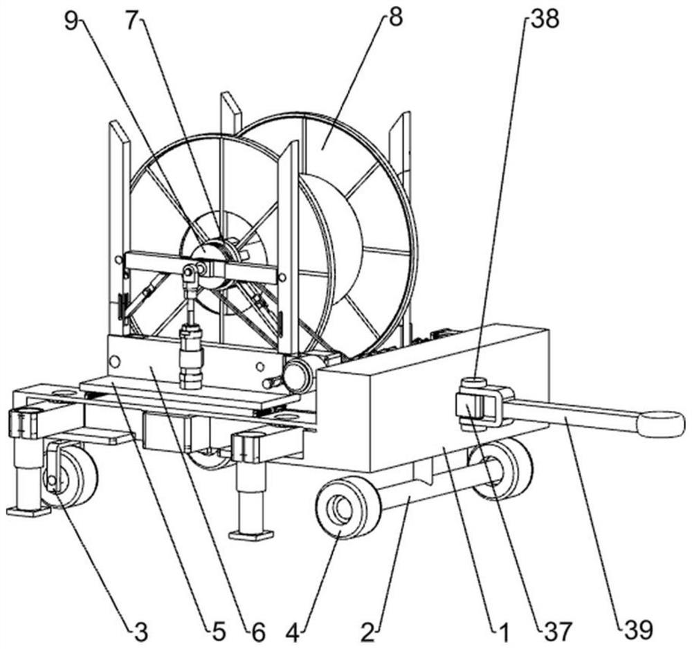
[0026] The present invention will be described in further detail below in conjunction with accompanying drawing and specific embodiment

[0027] figure 1 The first three-dimensional structure schematic diagram of the present invention, a pay-off device for optical cable laying includes: car body 1, slide rail 101, T-shaped wheel frame 2, universal wheel 3, caster 4, sliding plate 5, rectangular mounting block 6 , fixed pawl 7, optical cable reel 8, first rotating shaft 801, power unit, elevating device and adjusting device, T-shaped wheel frame 2 is installed on the right side of car body 1 bottom, and T-shaped wheel frame 2 front and rear sides are all rotatably connected with a Caster 4, a universal wheel 3 is installed on the front and rear sides of the left side of the bottom of the car body 1, and two slide rails 101 are symmetrically installed on the front and rear sides of the top of the car body 1, and the slide rail 101 is slidably connected with a slide plate 5. 5. ...


PUM


Abstract

The invention provides a pay-off device capable of facilitating installation and laying of an optical cable tray. The pay-off device for optical cable laying comprises a vehicle body, sliding rails, a T-shaped wheel frame, universal wheels, trundles, sliding plates, rectangular installation blocks, a fixing claw and the like. The T-shaped wheel frame is installed on one side of the bottom of the vehicle body, the trundles are rotationally connected to the two sides of the T-shaped wheel frame, the universal wheels are installed on the two sides of the other side of the bottom of the vehicle body, the sliding rails are fixedly installed on the two sides of the top of the vehicle body, the sliding plates are slidably connected to the sliding rails, the rectangular installation blocks are symmetrically installed on the inner sides of the sliding plates, and lifting devices are symmetrically arranged on the rectangular installation blocks. The lifting devices are symmetrically and rotationally connected with first rotating shafts, and one of the first rotating shafts is fixedly connected with the fixing claw. The effects of automatic lifting and adjustment of the distance between installation frames are achieved, the height of the installation frames for installing the optical cable tray is adjusted through the lifting devices, the optical cable tray can be installed on a wire barrow without lifting the optical cable tray, and the optical cable tray is convenient to load and unload.

Description

technical field [0001] The invention relates to a pay-off device, in particular to a pay-off device for optical cable laying. Background technique [0002] With the advent of the information age, the development of various industries in our country is closely related to communication technology. Therefore, both enterprises and people have high requirements for communication level, and the development speed of the communication industry is also very fast. The quality of communication technology is directly related to the current communication optical cable lines. Use hoisting equipment to place the optical cable reel on the pay-off vehicle, and then manually align the shaft and the optical cable reel for installation. This installation method has potential safety hazards, and it is easy for the hoisted optical cable reel to bump into the workers, and the installation time is longer. Time-consuming and labor-intensive, there is the problem of loading difficulties. [0003] F...

Claims


Application Information

Patent Timeline
Patent Type & Authority Applications(China)
IPC IPC(8): B65H49/38B65H49/36
CPCB65H49/38B65H49/36
Inventor 李松涛
Owner 李松涛
Features
  • R&D
  • Intellectual Property
  • Life Sciences
  • Materials
  • Tech Scout
  • Unparalleled Data Quality
  • Higher Quality Content
  • 60% Fewer Hallucinations
Learn More