AI technical title is built by PatSnap AI team. It summarizes the technical point description of the patent document.
A self-sealing and filter technology, applied in the field of air deodorization, which can solve the problems of water droplets breeding bacteria and air quality degradation.
Active Publication Date: 2022-05-06
山东林耀生物科技有限公司
View PDF0 Cites 0 Cited by
Summary
Abstract
Description
Claims
Application Information
AI Technical Summary
This helps you quickly interpret patents by identifying the three key elements:
Problems solved by technology
Method used
Benefits of technology
Problems solved by technology
[0003] If the air deodorizing filter with self-sealing blades is placed in a humid area such as a bathroom, and the exhaust fan will continue to rotate due to inertial force when it stops running, so that the water vapor in the bathroom will be sucked in by the exhaust fan when the sealing blades are closed. And the condensed water droplets on the leaves, if not cleaned in time, the water droplets are prone to breedbacteria, and the quality of the discharged air will decline when the filter is used again
Method used
Image
Click on the blue label to locate the original text in one second.
Reading with bidirectional positioning of images and text.
Examples
Embodiment 1
[0026] For example figure 1 -example Figure 5 Shown:
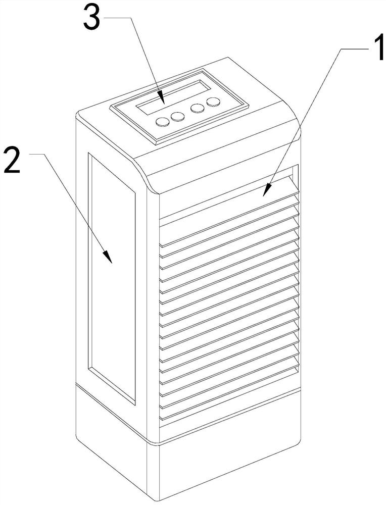
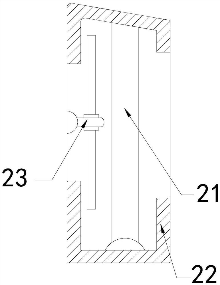
[0027] The present invention provides an air deodorizing filter with a self-sealing device, the structure of which includes a sealing blade 1, a body 2, and a control panel 3, the sealing blade 1 is movably engaged with the front end of the body 2, and the body 2 is connected to the control panel The panel 3 is an integrated structure; the body 2 includes a filter layer 21, an outer frame 22, and an air exhaust fan 23, the filter layer 21 is embedded in the inner wall of the outer frame 22, and the air exhaust fan 23 is installed on the outer frame 22 on the left side of the inner wall.
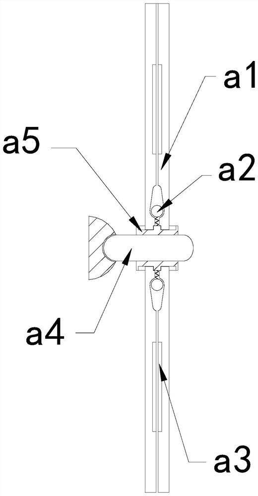
[0028] Wherein, the exhaust fan 23 includes a blade a1, an extruding ball a2, an adsorption plate a3, a connecting rod a4, and a fixed block a5. The blade a1 is movably engaged with the side of the fixed block a5, and the extruding ball a2 is installed between the two blades a1, the adsorption plate a3 and the blade a1 are an integrat...
Embodiment 2
[0034] For example Image 6 -example Figure 8 Shown:
[0035] Wherein, the connecting rod a4 includes a protruding block c1, a rotating shaft c2, and a base c3, the protruding block c1 is engaged with the inner part of the rotating shaft c2, and the rotating shaft c2 is connected to the right side of the laying base c3, There are two protruding blocks c1, which are evenly distributed symmetrically on the upper and lower sides of the rotating shaft c2. Through the force generated by the rotation of the mechanism, the protruding block c1 can be made to protrude outward along the rotating shaft c2, and the mechanism stops When rotating, the protruding block c1 can shrink by its own gravity, so that vibration can be generated to shake off part of the water droplets on the outer surface of the protruding block c1.
[0036] Wherein, the protruding block c1 includes an upper suction plate c11, a connecting piece c12, a linkage rod c13, and a bottom connecting block c14. Between t...
PUM
Abstract
The invention discloses an air deodorizing filter with a self-sealing device. The structure includes a sealing blade, a body, and a control panel. The sealing blade is movably engaged with the front end of the body. Reset to the extreme and collide with each other, so that vibration can be generated to guide the water droplets on the outer surface of the blades into the collection chamber for collection, and then the water droplets collected in the fixed plate can be collected through the water absorption block, effectively avoiding the stop of the exhaust fan After operation, water vapor will be sucked in, resulting in water droplets adhering to the outer surface of the blade. Through the vibration generated by the reset of the protruding block, the upper suction plate can swing upwards with the cooperation of the linkage rod, so that the upper suction plate can move Part of the moisture is removed, and the moisture that cannot be removed in time can be absorbed through the upper suction plate.
Description
technical field [0001] The invention relates to the field of air deodorization, in particular to an air deodorization filter with a self-sealing device. Background technique [0002] The air deodorizing filter with self-sealing blades is mainly used to purify and filter indoor air. The indoor air can be sucked in by the rotation of the internal exhaust fan, and then the harmful substances in the air can be filtered through the filter layer. , and the sealing blade can be automatically closed when the air deodorizing filter stops running, so as to prevent external pollutants from entering the air deodorizing filter, and it takes a certain time for the sealing blade to be completely closed, based on the above description The inventor found that the existing air deodorization filter with a self-sealing device mainly has the following deficiencies, for example: [0003] If the air deodorizing filter with self-sealing blades is placed in a humid area such as a bathroom, and the ...
Claims
Application Information
Patent Timeline
Application Date:The date an application was filed.
Publication Date:The date a patent or application was officially published.
First Publication Date:The earliest publication date of a patent with the same application number.
Issue Date:Publication date of the patent grant document.
PCT Entry Date:The Entry date of PCT National Phase.
Estimated Expiry Date:The statutory expiry date of a patent right according to the Patent Law, and it is the longest term of protection that the patent right can achieve without the termination of the patent right due to other reasons(Term extension factor has been taken into account ).
Invalid Date:Actual expiry date is based on effective date or publication date of legal transaction data of invalid patent.

