A fixation device for bone rehabilitation of lower leg
A bone fixation and bone technology, applied in fractures, non-surgical orthopaedic surgery, medical science, etc., can solve problems such as walking inconvenience, water-intake wound infection, plaster sinking, etc., to achieve the effect of light material and avoid infection
- Summary
- Abstract
- Description
- Claims
- Application Information
AI Technical Summary
Problems solved by technology
Method used
Image
Examples
Embodiment 1
[0027] A fixation device for calf skeletal rehabilitation, such as image 3 As shown, it includes a bone fixation rod 1, an annular block 2, a gathering mechanism 3 and a shrinking mechanism 4. A plurality of bone fixation rods 1 are fixed with annular blocks 2 at intervals, and the annular block 2 is provided with a gathering mechanism 4. The gathering mechanism 3 is provided with a retracting mechanism 4 .
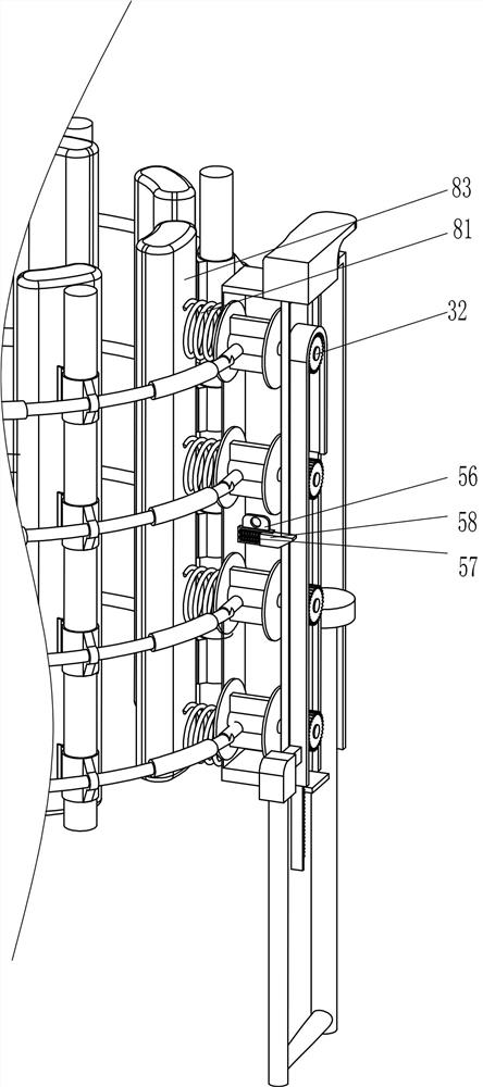
[0028] The gathering mechanism 3 includes a first fixing block 31 , a shrinking line 32 and a fixing ring 33 , a first fixing block 31 is fixedly connected to the outer side of the annular block 2 , and a shrinking line 32 is arranged between the outside of the corresponding first fixing block 31 to shrink Fixed rings 33 are provided at intervals on the wire 32 .
[0029] The shrinking mechanism 4 includes a rectangular frame 41, a rotating shaft 42 and a shrinking wheel 43. A rectangular frame 41 is provided at the front of the shrinking wire 32. The rectangular frame ...
Embodiment 2
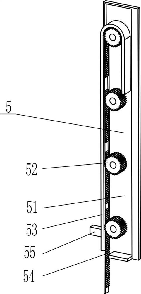
[0032] On the basis of Example 1, as Figure 5 and Image 6 As shown, it also includes an adjustment mechanism 5, and the adjustment mechanism 5 includes a guide frame 51, a column gear 52, a guide groove plate 53, a missing rack 54, a toggle block 55, a second fixed block 56, a first spring 57 and a first A clamping block 58, a guide frame 51 is fixedly connected to the front side of the rectangular frame 41, and a column gear 52 is arranged on the guide frame 51 to rotate at intervals. A guide groove plate 53 is connected, the guide groove plate 53 is slidably provided with a missing gear rack 54, the missing gear rack 54 is engaged with the column gear 52, the lower left side of the guide frame 51 is slidably provided with a toggle block 55, and the toggle block 55 The right side is fixedly connected to the lower part of the left side of the missing rack 54 , the middle of the left side of the rectangular frame 41 is fixedly connected with a second fixing block 56 , and th...
Embodiment 3
[0037] On the basis of Example 1 and Example 2, as figure 1 , figure 2 and Figure 7 As shown, it also includes a fine adjustment device 7, the fine adjustment device 7 includes a second spring 71, a hinge block 72 and a fourth fixed block 73, the inner side of the annular block 2 is fixed with a hinge block 72, the hinge block 72 in the same row is outside A fourth fixing block 73 is fixedly connected between the side surfaces, and a second spring 71 is fixedly connected between the fourth fixing block 73 and the inner side surface of the annular block 2 .
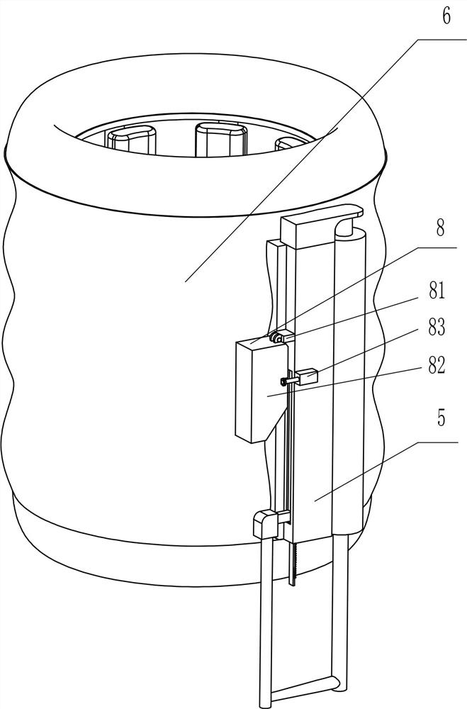
[0038] It also includes a protective device 8. The protective device 8 includes a fifth fixing block 81, a protective frame 82 and a second clamping block 83. The upper left side of the guide frame 51 is fixed with a fifth fixing block 81, and the left side of the fifth fixing block 81 is fixed. A protective frame 82 is provided in the hinged part, and a second blocking block 83 is fixed in the middle of the left part of...
PUM
 Abstract
Description
Claims
Application Information
 - R&D
- Intellectual Property
- Life Sciences
- Materials
- Tech Scout
- Unparalleled Data Quality
- Higher Quality Content
- 60% Fewer Hallucinations
Browse by: Latest US Patents, China's latest patents, Technical Efficacy Thesaurus, Application Domain, Technology Topic, Popular Technical Reports.
© 2025 PatSnap. All rights reserved.Legal|Privacy policy|Modern Slavery Act Transparency Statement|Sitemap|About US| Contact US: help@patsnap.com


