Automatic cleaning system for electrical cabinet cleaning

A technology for automatic cleaning and electrical cabinets, applied in the direction of using liquid cleaning methods, cleaning methods and utensils, chemical instruments and methods, etc., can solve the inconvenience of manual cleaning of electrical cabinets, etc., to save costs, reduce failure rates, and ensure stability. sexual effect

Active Publication Date: 2021-06-08
ANHUI UNIVERSITY OF TECHNOLOGY
View PDF13 Cites 0 Cited by
  • Summary
  • Abstract
  • Description
  • Claims
  • Application Information

AI Technical Summary

Problems solved by technology

[0009] The purpose of the present invention is to overcome the inconvenience of manual cleaning of electrical cabinets in the prior art, and to provide an automatic cleaning system for cleaning electrical cabinets, which helps to clean electrical cabinets comprehensively and efficiently, reduces cleaning costs, improves cleaning efficiency, and reduces Worker's labor intensity

Method used


Image

  • Automatic cleaning system for electrical cabinet cleaning
  • Automatic cleaning system for electrical cabinet cleaning
  • Automatic cleaning system for electrical cabinet cleaning

Examples


Embodiment 1

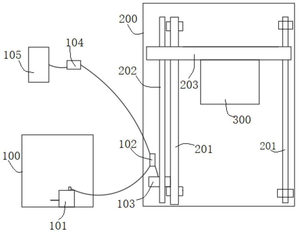
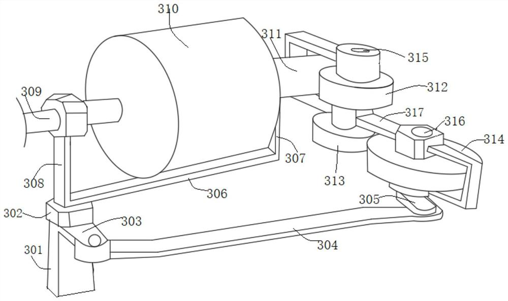
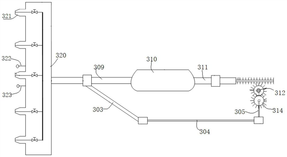
[0035] Such as Figure 1-Figure 4 As shown, an automatic cleaning system for cleaning electrical cabinets in this embodiment includes a cleaning unit 200. The cleaning unit 200 includes transmission belts 201 distributed on both sides along the height direction of the electrical cabinet and used for transmission. The transmission belts 201 on both sides are arranged There is a crossbeam 203, which can be fastened by screws between the concrete crossbeam 203 and the transmission belt 201; the crossbeam 203 is provided with multiple groups of shower heads 320, and each group of nozzle holders 320 is provided with at least one nozzle 321, and the transmission belt 201 is used to drive the crossbeam 203 and The nozzles 321 rise and fall along the height direction; each group of nozzle holders 320 is also equipped with a temperature sensor 322 and a density sensor 323, which are specifically temperature sensors and density sensors for air detection, and are used to detect the intern...

Embodiment 2

[0049] An automatic cleaning system for cleaning electrical cabinets in this embodiment is basically the same as in Embodiment 1. Further, an infrared thermal imager is also provided on the beam 203 for subsequent inspections. In actual use, step S3 follows After the first cleaning of the quality of the cleaning solution that fits the information, an infrared thermal imager is used to inspect the electrical cabinet again, and the temperature and density information of the grid area that is still heating is detected again, and its temperature rise is compared with the initial Compared with the temperature rise, if the error is less than 3%, the cleaning is up to standard; if the error is still greater than 3%, continue to clean according to the quality of the cleaning solution that is not less than the fitting, and if the grid area still cannot meet the standard after 3 inspections, record The location information judges the failure of the grid area, which is used for confirmati...

Embodiment 3

[0051] An automatic cleaning system for cleaning electrical cabinets in this embodiment is basically the same as in Embodiment 2. Furthermore, in this embodiment, the beam 203 is also provided with a nozzle adjustment unit for adjusting the spray angle of each group of nozzle holders 320 300, so that during spray cleaning, the spray angle can be flexibly adjusted to achieve a better spray effect. Specifically, the nozzle adjustment unit 300 can be driven by a motor, and the output shaft end of the motor is connected to the nozzle frame 320. By controlling the motor The angle of the nozzle holder 320 can be reversed by forward and reverse rotation, so as to realize the change of the angle of spray cleaning and meet the needs of actual use.


PUM


Abstract

The invention discloses an automatic cleaning system for electrical cabinet cleaning, and belongs to the field of electrical equipment cleaning. The automatic cleaning system comprises a cleaning unit, wherein the cleaning unit comprises transmission belts distributed on the two sides in the height direction of an electrical cabinet, a cross beam is arranged between the transmission belts on the two sides, at least one nozzle frame is arranged on the cross beam, at least one nozzle is arranged in each nozzle frame, and the transmission belts are used for driving the cross beam to ascend and descend in the height direction; and a temperature sensor and a density sensor are also arranged on each nozzle frame. The automatic cleaning system for electrical cabinet cleaning overcomes the defect that in the prior art, manual cleaning of the electrical cabinet is inconvenient, comprehensive and efficient cleaning of the electrical cabinet is facilitated, the cleaning cost is reduced, the cleaning efficiency is improved, and the labor intensity of operators is reduced.

Description

technical field [0001] The invention relates to the technical field of electrical equipment cleaning, and more specifically relates to an automatic cleaning system for cleaning electrical cabinets. Background technique [0002] With the construction of an intelligent information society, the power system has been rapidly developed and expanded. The electrical cabinet is the basic component of the power system's transmission and distribution of current, which is crucial to the safety and reliability of the power system. It has been widely used in the market. However, due to the influence of the working environment of the electrical cabinet, the electrical cabinet that has been left standing for a long time is easy to accumulate dust, and the dust accumulated on the surface of the electrical equipment will increase the heat dissipation thermal resistance of the electrical equipment, reduce the insulation performance of the electrical equipment, and cause a fire in the electrica...

Claims


Application Information

Patent Timeline
Patent Type & Authority Applications(China)
IPC IPC(8): B08B3/02B08B13/00
CPCB08B3/02B08B13/00
Inventor 陆彪汤凯王昭陈德敏
Owner ANHUI UNIVERSITY OF TECHNOLOGY
Why Eureka
Try Eureka