Cantilever erection of large-span railway steel truss girder bridge with flexible cushioning device for ultra-high load-bearing brackets

A steel truss bridge and long-span technology, which is applied in the erection/assembly of bridges, bridge construction, bridges, etc., can solve the problems of high construction cost, uneven pad steel plate, harsh use conditions, etc., and achieves high safety and cost. Low, adaptable effects

Active Publication Date: 2022-06-03
CHINA TIESIJU CIVIL ENG GRP CO LTD +1
View PDF10 Cites 0 Cited by
  • Summary
  • Abstract
  • Description
  • Claims
  • Application Information

AI Technical Summary

Problems solved by technology

[0011] Pure steel plate copying pad, the investment cost of copying pad is low, but it can’t solve the problem of eccentric bending moment and rotation angle well, the vertical force transmission is concentrated on one side of the cantilever, and because of the rotation angle, the actual supporting area of ​​the bracket is narrow, and one side of the bracket (or single component) side) the force is too large, the investment cost of the support will increase, and the cost of the overall solution will increase instead.
In actual construction, the uneven steel plate of the copying pad may cause "point-to-point" force transmission between the bridge and the copying pad, and the part should be too large, resulting in a high safety risk
[0012] The use of bridge hinge support pads can effectively solve the problem of vertical force eccentricity, and at the same time adapt to the corner, but the construction cost of bridge hinge support is high, it is difficult to reuse, and the use conditions are harsh

Method used


Image

  • Cantilever erection of large-span railway steel truss girder bridge with flexible cushioning device for ultra-high load-bearing brackets
  • Cantilever erection of large-span railway steel truss girder bridge with flexible cushioning device for ultra-high load-bearing brackets
  • Cantilever erection of large-span railway steel truss girder bridge with flexible cushioning device for ultra-high load-bearing brackets

Examples


Embodiment Construction

[0035] The technical solutions in the embodiments of the present invention will be described clearly and completely below. Obviously, the described implementation

[0036] It should be noted that all directional indications (such as up, down, left, right, front, back...) in the embodiments of the present invention

[0037] In addition, in the present invention, such as the description related to "first", "second", etc. are only for the purpose of description, and should not be construed as

[0039] The present invention will now be further described with reference to the accompanying drawings.

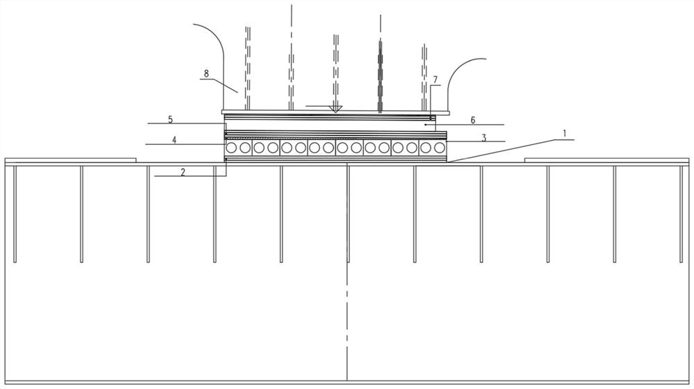
[0043] The plate type rubber bearing should give a suitable plane size (the length and width of the rubber bearing) before processing to make it fully covered

[0045]

[0047] Wedge-shaped steel plate: The wedge-shaped steel plate is a local "fine-tuning" structure of the flexible pad device. Due to the actual erection process and


PUM


Abstract

The invention discloses a flexible cushioning device for superhigh load-bearing brackets erected by cantilever erection of large-span railway steel truss girder bridges. The first backing steel plate and cast steel plate, the rubber bearing includes the second backing steel plate, rubber pad, and third backing steel plate connected in sequence from the bottom, the first backing steel plate, the second backing plate Both the backing steel plate and the third backing steel plate adopt three-layer steel plate. The device of the invention contains a plate-type rubber bearing and a wedge-shaped steel plate to solve the problems of eccentricity and rotation angle, and also has the advantages of high safety, low cost of pad copying, and strong adaptability.

Description

Flexible pad device for cantilever erection of ultra-high load-bearing brackets for long-span railway steel truss bridges technical field The invention belongs to bridge design field, relate in particular to long-span railway steel truss bridge cantilever erection super high load-bearing support Flexible copy pad device. Background technique [0002] The large-span railway bridges in mountainous areas are mostly suspension bridges and cable-stayed bridges, and the construction of the cable structure is difficult and the maintenance cost is high in the later period. Big Span continuous steel truss girder structure will be more and more used in mountain bridges. Good plasticity and toughness have great advantages in bridges spanning rivers, valleys and existing lines. Steel truss girder structure construction can generally select sling tower cantilever erection and support method cantilever according to construction site conditions. erection. When the ground conditio...

Claims


Application Information

Patent Timeline
Patent Type & Authority Patents(China)
IPC IPC(8): E01D21/10E01D21/00
CPCE01D21/10E01D21/00
Inventor 张伟曹晗谢露丁仕洪郭晓崔洪岩王炳岩黄晨东康志凯欧阳石丁鹤高金平
Owner CHINA TIESIJU CIVIL ENG GRP CO LTD
Why Eureka
Try Eureka