Stirling engine

A Stirling engine, linear motion technology, applied in the direction of machine/engine, hot gas variable capacity engine device, mechanical equipment, etc., can solve the problems of thermal cylinder parameter design limitation, high cost, overall complexity, etc., to achieve overall aesthetics The effect of raising and lowering the overall height and facilitating reasonable arrangement

Active Publication Date: 2015-09-23
苏州欣旺达创业服务有限公司
View PDF9 Cites 0 Cited by
  • Summary
  • Abstract
  • Description
  • Claims
  • Application Information

AI Technical Summary

Problems solved by technology

[0003] However, the flywheels of the above-mentioned Stirling engines are all set perpendicular to the direction of motion of the power piston. This setting will cause the height of the overall Stirling engine to be too high. In some occasions that limit the overall height of the Stirling engine, the parameters of the upper part of the hot cylinder design is often limited
In addition, the flywheel generally needs to be supported by an independent bracket, which makes the overall complex, heavy, and costly, and the brackets are generally set eccentrically, resulting in poor symmetry of the Stirling engine, so there is a shortcoming of insufficient overall aesthetics

Method used


Image

  • Stirling engine
  • Stirling engine
  • Stirling engine

Examples


Embodiment 1

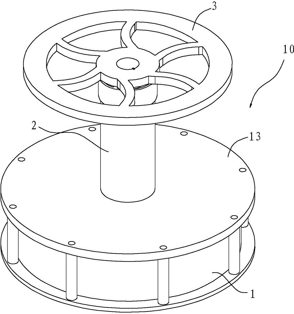
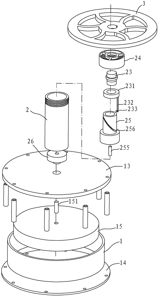
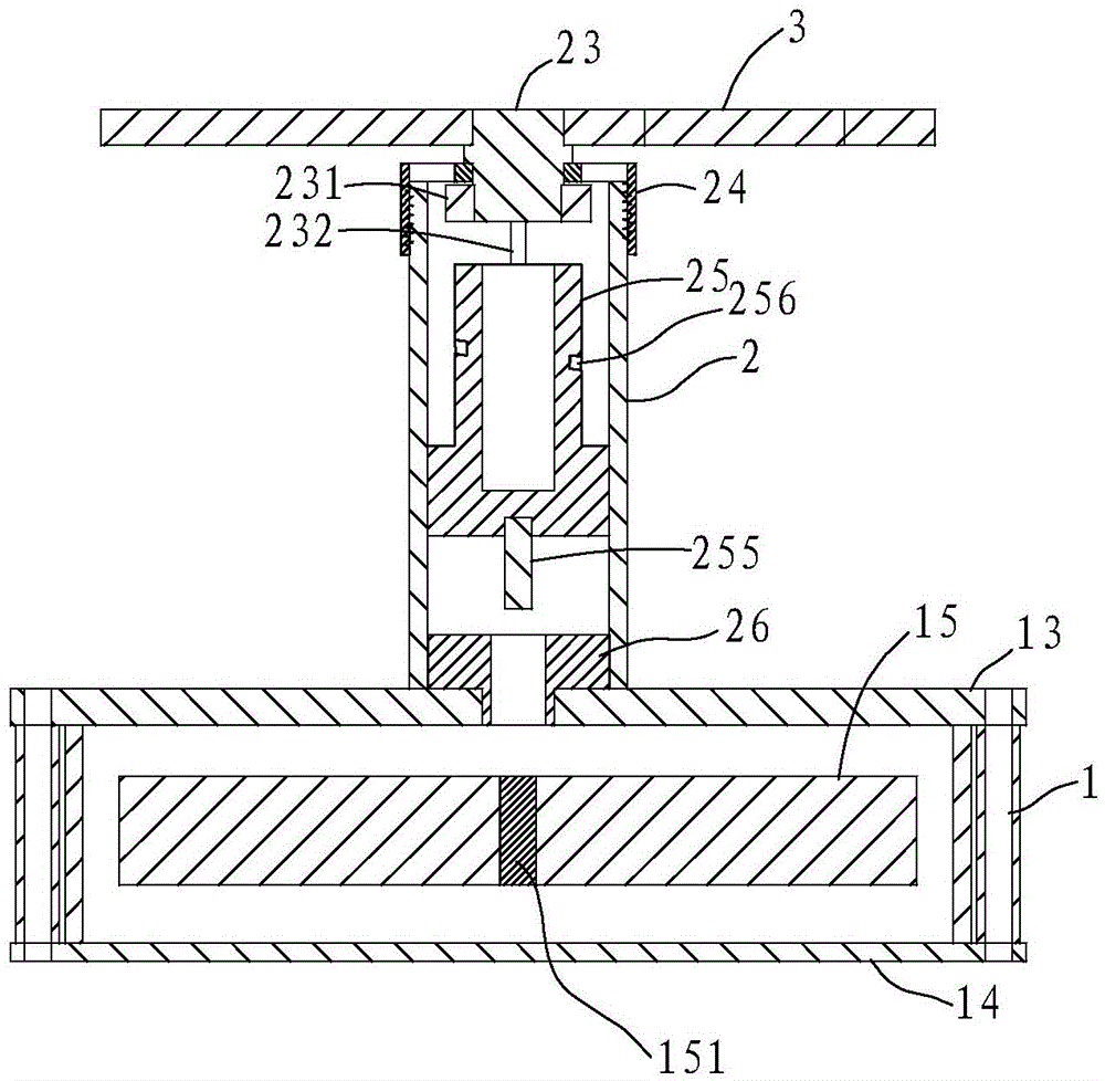
[0033] like Figure 1~4 As shown, the Stirling engine 10 includes a first cylinder 1, a second cylinder 2, a first piston 15 (displacement piston) and a second piston 25 (power piston), and the first cylinder 1 has a heat dissipation surface 13 and a heat absorption surface 14. The Stirling engine 10 is a low-temperature differential Stirling engine, and the heat-absorbing surface 14 absorbs energy so that the volume of the first cylinder 1 expands and pushes the first piston 15 .

[0034] The bottom end of the second piston 25 of the Stirling engine 10 is provided with a magnet 255 , and a guide groove 256 is obliquely formed on the outer periphery of the second piston 25 . Or, alternatively, the middle part of the second piston 25 can also be formed hollow, and the guide groove 256 can be formed on the inner wall. However, it is preferred to form the guide groove 256 on the outer periphery.

[0035] The first piston 15 is provided with a driving block 151 which cooperates...

Embodiment 2

[0045] like Figure 5 As shown, in this embodiment, in this embodiment, the difference from Embodiment 1 is that in this embodiment, the way to prevent the rotation of the second piston 25 is that the cross section of the second cylinder 2 is square, correspondingly, the first The cross section of the two pistons 25 is also square. The square design can limit the rotation of the second piston 25 to ensure that the second piston 25 can move up and down.

Embodiment 3

[0047] like Figure 6 ~ Figure 8 , in this embodiment, the difference from the above-mentioned embodiment 1 is that in the second cylinder 2, a rotating block 29 is arranged above the second piston 25 and below the cover 24, and the rotating shaft 23 runs through the rear end of the cover 24 It is connected with the rotating block 29 and rotates synchronously. On the second piston 25, the first magnet unit 251 and the second magnet unit 252 are arranged at intervals such as the upper end surface, and on the rotating block 29, the third magnet unit 291 and the fourth magnet unit 292 are arranged at intervals on the lower end surface, in each magnet unit A plurality of magnets with the same magnetic poles may be included, the first magnet unit 251 and the second magnet unit 252 have opposite magnetic poles, and the third magnet unit 291 and the fourth magnet unit 292 have opposite magnetic poles.

[0048] After an initial power is given to the flywheel 3, the first magnet unit ...


PUM


Abstract

The invention discloses a Stirling engine which comprises a first air cylinder, a second air cylinder, a first piston, a second piston and a flywheel. The first air cylinder and the second air cylinder are communicated with each other. The first piston is arranged in the first air cylinder and moves in a straight-line mode. The second piston is arranged in the second air cylinder and moves in a straight-line mode. The Stirling engine is characterized in that a magnet is arranged at the bottom end of the second piston, a driving block which is matched with the magnet in a gap-type-attracting mode is arranged on the first piston. The flywheel is arranged at the top end of the second air cylinder horizontally through a rotating shaft. The rotating shaft is driven to rotate by the second piston. A guiding groove is formed in the outer periphery or the inner wall of the second piston obliquely. A driving rod is connected below the rotating shaft. The end of the driving rod is arranged in the guiding groove and can move along the guiding groove. The flywheel is arranged horizontally, the overall height is greatly lowered, reasonable arrangement of other parts is convenient, special support arrangement is removed for the flywheel, the eccentric problem is solved, and overall attractiveness is improved.

Description

technical field [0001] The invention relates to an engine, especially a Stirling engine. Background technique [0002] As we all know, the Stirling engine is an external combustion engine, which avoids the detonation work and intermittent combustion process similar to the internal combustion engine, and has the advantages of high efficiency, low noise and low emission. The cycle process involved in its basic principle is divided into the following four stages: ①Constant temperature compression process; ②Constant volume heat absorption process; ⑧Constant temperature expansion process; ④Constant volume exothermic process, complete a cycle. Under ideal endothermic conditions, the thermal efficiency of this cycle is equal to the Carnot cycle with the same upper and lower temperature limits. Similar reference can be made to the Chinese invention patent "Low Temperature Difference Stirling Engine Model" (notification number CN202795860U) with patent number ZL201220515490.X, and s...

Claims


Application Information

Patent Timeline
Patent Type & Authority Applications(China)
IPC IPC(8): F02G1/044F02G1/053
CPCA47G19/2205A47G19/24F02G1/043F02G1/044F02G1/053
Inventor 魏亮
Owner 苏州欣旺达创业服务有限公司
Why Eureka
Try Eureka