
Roughness detection tool

A technology for detecting tooling and roughness, which is applied to measurement devices, instruments, etc., can solve the problems of small measurement range, small measurement data, difficulty in ensuring measurement accuracy, poor measurement accuracy, etc., to achieve convenient adjustment and operation, and reliable measurement stability. Good performance and improved accuracy

Active Publication Date: 2021-06-08
NINGBO YUNDE MATERIALS INC
View PDF7 Cites 1 Cited by
  • Summary
  • Abstract
  • Description
  • Claims
  • Application Information

AI Technical Summary

Problems solved by technology

The surface roughness of traditional quartz parts is measured with a hand-held roughness meter. The operation is more complicated, there are certain errors, and the measurement accuracy is poor.
Some existing roughness testing tools have problems such as relatively single roughness measurement position, small measurement range, inconvenient operation and adjustment, and little measurement data to ensure measurement accuracy.

Method used


Image

  • Roughness detection tool
  • Roughness detection tool
  • Roughness detection tool

Examples


Embodiment 1

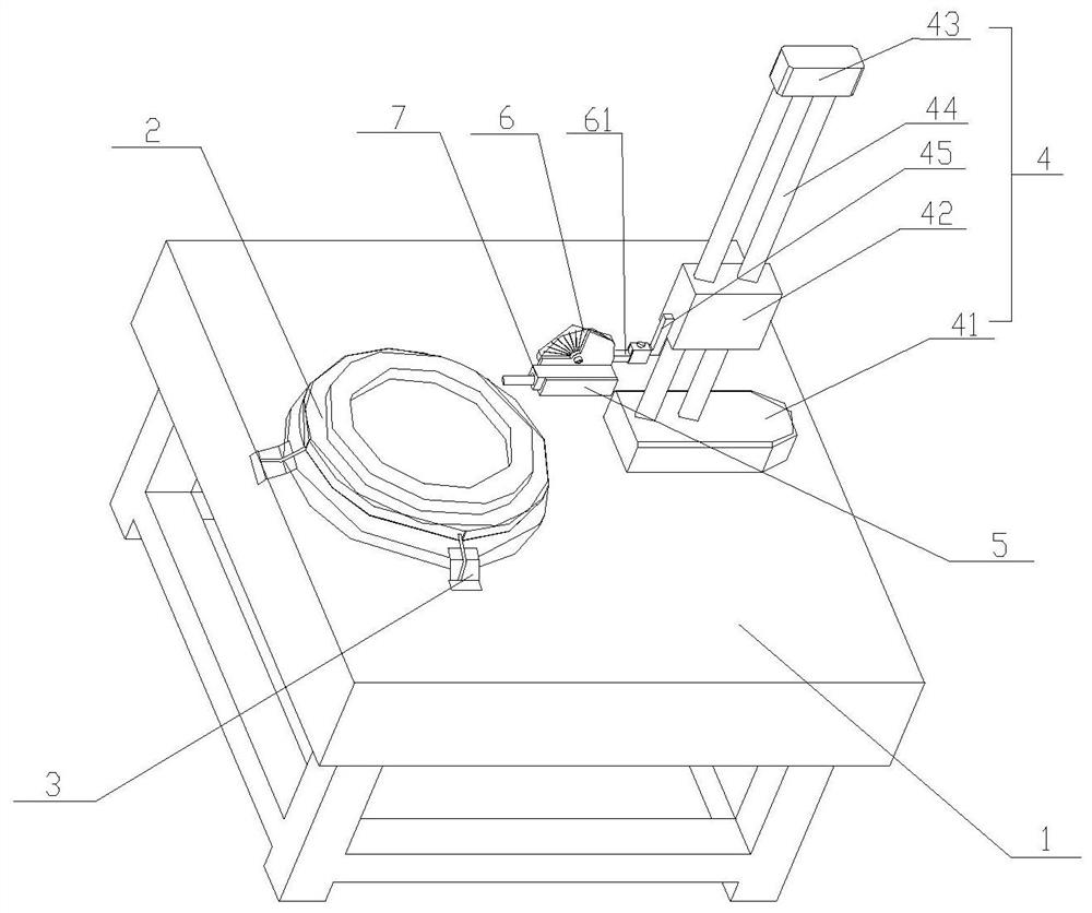
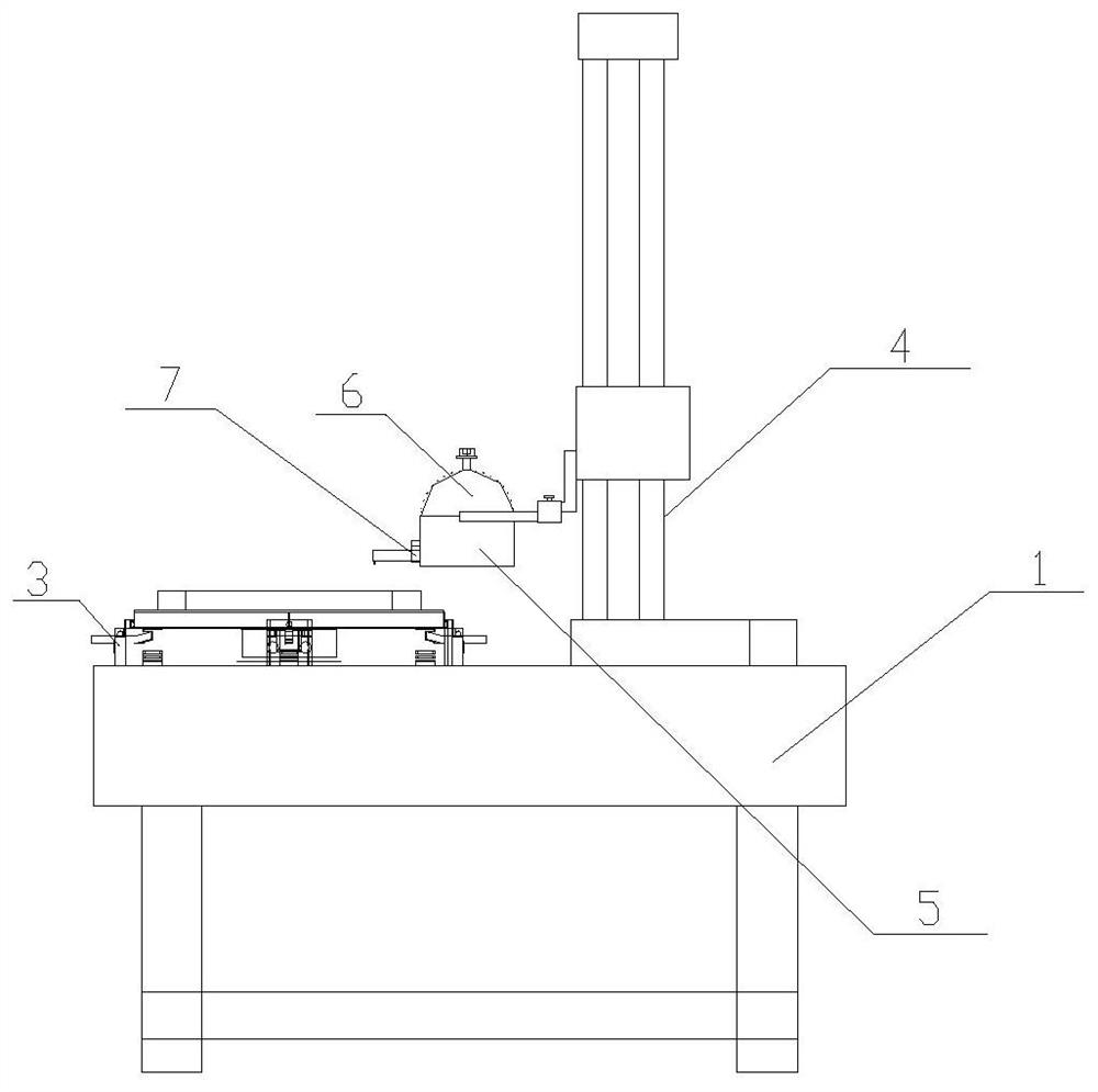
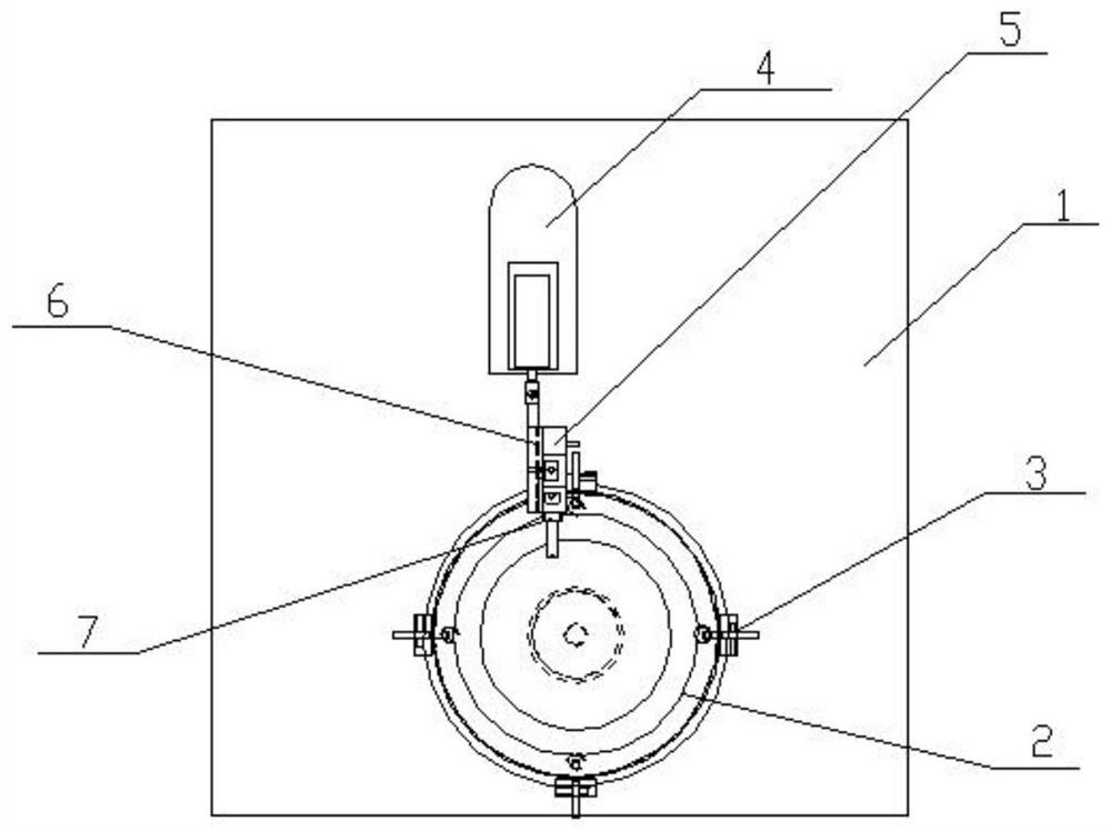
[0028] Embodiment 1 refers to Figure 1 to Figure 6 , this embodiment provides a roughness detection tool, including a frame 1, a locking device 3, a roughness detection device, a turntable 2 installed on the frame 1, and a lifting platform 4, and the lifting platform 4 includes a lower support seat 41 , the upper support seat 43, the guide rail 44 is installed between the lower support seat 41 and the upper support seat 43, the lifting seat 42 that can move up and down is installed on the guide rail 44, and the side wall of the turntable 2 is provided with some arc-shaped draw grooves 21, locking The device 3 includes a bracket and a card tube installed on the bracket. A spring 31 with a spring ball head 32 at the end is installed inside the card tube. The spring ball head 32 can be snapped into the corresponding arc shape after the turntable 2 rotates at a corresponding angle. In the slot 21, the roughness detection device includes a dial 6, a measuring table 5 and a roughne...

Embodiment 2

[0035] Embodiment 2, except that an electric push rod is installed on the lower support base 41, and the push rod end of the electric push rod is connected with the bottom surface of the lifting seat 42, all the other structures are the same as in Embodiment 1.

Embodiment 3

[0036] Embodiment 3, except that the turntable driving device is installed on the frame 1, the turntable driving device includes a servo motor, the output end of the servo motor is connected with the bottom surface of the lower turntable, and the servo motor can control the rotation of the turntable to keep at 90° each time, the rest of the structure Same as Example 1.


PUM


Abstract

A roughness detection tool disclosed by the invention comprises a rack, a locking device, a roughness detection device, a rotary table and a lifting table. The rotary table can be clamped by the locking device after the rotary table rotates by a corresponding angle, the roughness detection device comprises a dial, a measurement table and a roughness instrument, the front surface of the dial is provided with scales and scale values, a connecting rod is arranged on the back surface of the dial and detachably connected with one side of a lifting seat, a rotating gear shaft is arranged between the measurement table and the front surface of the dial, a stand column with a marking arrow is arranged on the measurement table, and the measurement table rotates around the rotating gear shaft by a certain angle and then is fixed so that an included angle can be formed between the measurement table and the dial. The included angle is equal to the scale value, pointed to the dial, of the marking arrow, and a roughness meter which can be placed in a horizontal overturning mode is installed on the measurement table in a matched mode. The tool has the advantages that the measuring position of the roughness meter can be adjusted in all directions according to measuring requirements, the measuring accuracy is high, and adjusting operation is convenient.

Description

【Technical field】 [0001] The invention belongs to the technical field of roughness detection devices, in particular to a roughness detection tool. 【Background technique】 [0002] Roughness detection tool is a kind of equipment used to measure the surface roughness of products, which is commonly used in the quartz production and processing industry. Due to the special role of quartz components in semiconductor devices, the requirements for surface roughness are relatively high in the design and processing of components. During the processing of quartz parts, it is necessary to measure multiple positions on the surface of the part, such as inclined plane position, inner diameter position, step position, horizontal position and vertical position, among which the measurement of inclined plane position, step position and inner diameter position is more special. The surface roughness of traditional quartz parts is measured with a hand-held roughness meter. The operation is more c...

Claims


Application Information

Patent Timeline
Patent Type & Authority Applications(China)
IPC IPC(8): G01B21/30
CPCG01B21/30
Inventor 冯剑秋
Owner NINGBO YUNDE MATERIALS INC
Learn More