Sliding rail assembly and bracket device thereof

A technology of bracket device and slide rail assembly, which is applied in the field of brackets and can solve problems such as inability to play the foolproof function

Active Publication Date: 2021-06-08
KING SLIDE WORKS CO LTD +1
View PDF6 Cites 0 Cited by
  • Summary
  • Abstract
  • Description
  • Claims
  • Application Information

AI Technical Summary

Problems solved by technology

However, if the case does not have a lock, it cannot play its fool-proof function

Method used


Image

  • Sliding rail assembly and bracket device thereof
  • Sliding rail assembly and bracket device thereof
  • Sliding rail assembly and bracket device thereof

Examples


Embodiment Construction

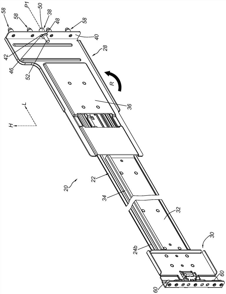
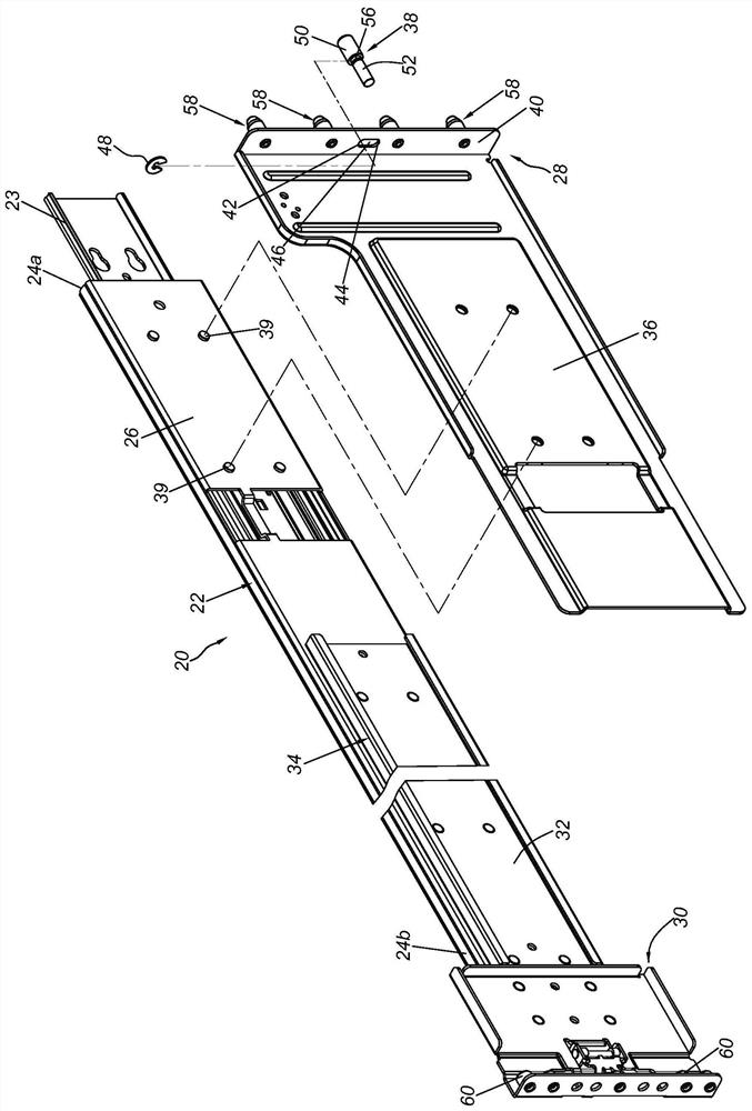
[0037] Such as figure 1 and figure 2 As shown, a sliding rail assembly 20 according to the embodiment of the present invention includes a rail 22 , preferably, at least one movable rail 23 telescopically connected to the rail 22 so as to be longitudinally displaceable relative to the rail 22 . The rail 22 has a first end portion 24a, a second end portion 24b and a longitudinal body 26 located between the first end portion 24a and the second end portion 24b. Wherein, a first bracket device 28 is arranged adjacent to the first end portion 24a, and a second bracket device 30 is arranged adjacent to the second end portion 24b.

[0038] Preferably, the rail 22 is configured with a reinforcing member 34 to facilitate the structural strength of the rail 22 , and the second bracket device 30 is connected to the rail 22 adjacent to the reinforcing member 34 . On the other hand, the first bracket device 28 is connected to the rail 22 . The first bracket device 28 includes a longitu...


PUM


Abstract

The invention relates to a sliding rail assembly and a bracket device thereof. The bracket device comprises a longitudinal wall and a mounting piece; the mounting piece can move along a height direction relative to the longitudinal wall; and when the bracket device is turned over by an angle from a first state to a second state, the mounting piece can move from a first position to a second position. When located at the first position, the mounting piece can be used for being installed on a rack. When located at the second position, the mounting piece cannot be installed on the rack.

Description

technical field [0001] The invention relates to a bracket, in particular to a bracket device for a slide rail. Background technique [0002] Generally speaking, the bracket device can be applied to a slide rail, so that the slide rail can be installed to a machine column of a rack through the bracket device. [0003] For example, US Patent Publication No. US 9,930,805 B2 discloses a bracket and its foolproof device. Wherein, the fool-proof device includes a slider and a positioning piece. as in the patent case Figure 4 and Figure 5 As shown, when a mounting seat of the bracket is turned over 180 degrees, the positioning member will naturally fall into a locking feature of the slider under gravity, so that the slider cannot freely displace relative to the mounting seat. When the bracket is at a first installation angle relative to the column, the bracket can be put on the shelf without being interfered by the fool-proof device. When the bracket is at a second installati...

Claims


Application Information

Patent Timeline
IPC IPC(8): H05K7/14
CPCH05K7/14H05K7/1489
Inventor 陈庚金杨顺和周继志王俊强
Owner KING SLIDE WORKS CO LTD
Why Eureka
Try Eureka