

A kind of one-way transmission gear structure
A gear structure, one-way transmission technology, applied in the field of transmission gears, can solve the problem of high cost of the one-way transmission gear structure, and achieve the effects of easy promotion and use, convenient use, and reduced use cost
- Summary
- Abstract
- Description
- Claims
- Application Information
AI Technical Summary
Problems solved by technology
Method used
Image

Examples
Embodiment 1
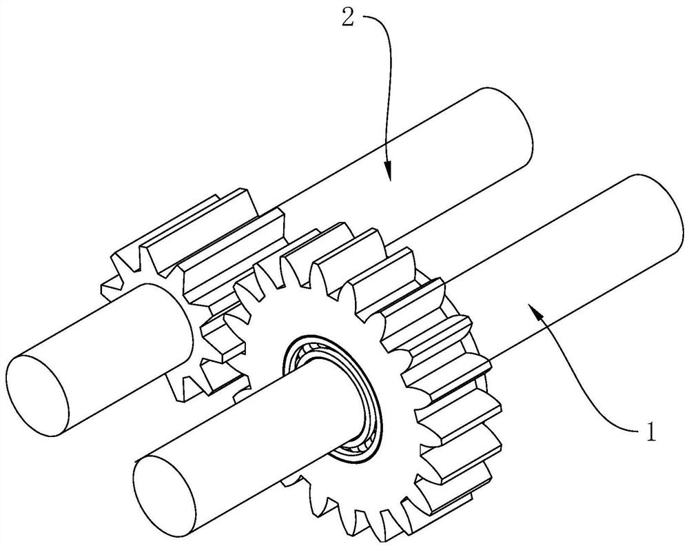
[0068] refer to figure 1 , the one-way transmission gear structure includes a driving gear 1 for connecting the motor and a driven gear 2 for connecting the movable parts. The driving gear 1 and the driven gear 2 are connected by meshing, and the driving gear is connected to the driving gear through the motor. 1 Input torque, and then transmit the torque to the driven gear 2 through the driving gear 1, so that the driven gear 2 can drive the movable part to do work.
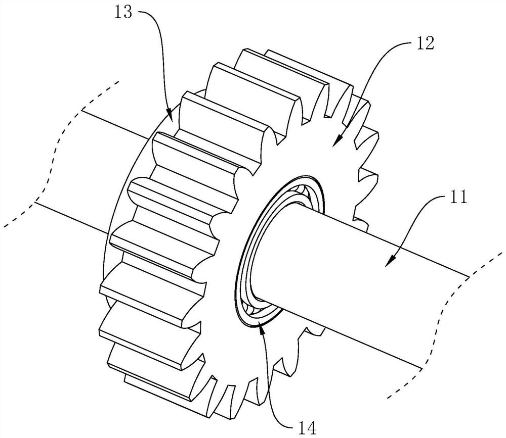
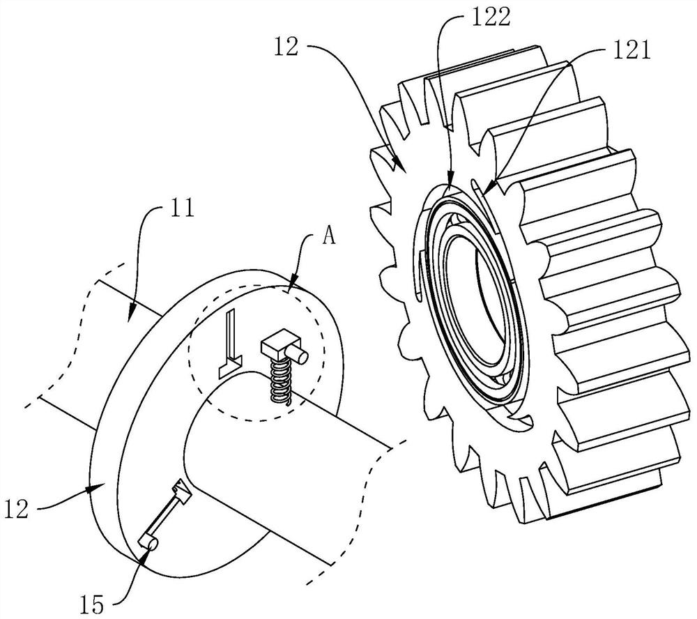
[0069] refer to figure 2 and image 3 , the driving gear 1 includes a transmission shaft 11, a gear body 12 and a limit wheel 13. The transmission shaft 11 is used to connect the motor to input torque, and the gear body 12 is sleeved on the transmission shaft 11 and is rotatably connected with the transmission shaft 11. The position wheel 13 and the transmission shaft 11 are relatively circumferentially fixed; wherein, a linkage assembly 15 is provided between the limit wheel 13 and the gear body 12, and the l...
Embodiment 2
[0082] Refer to push 6 and Figure 7 The difference between this embodiment and Embodiment 1 is that the lead-out structure 122 is set as a guide slope 124, the guide slope 124 is set in one end of the limit groove 121 close to the gear body 12, and the two sides of the guide slope 124 are respectively connected with the limit groove The two sides of the guide slope 121 are connected, the bottom of the guide slope 124 is connected with the bottom surface of the limit groove 121 , and the slope top of the guide slope 124 is connected with the side of the gear body 12 close to the limit wheel 13 .
[0083] refer to Figure 8 , the limit wheel 13 is fixedly connected with the transmission shaft 11, the limit rod 151 includes a sliding portion 155, a telescopic portion 156 and a second elastic member 157, and the end of the sliding portion 155 away from the gear body 12 is connected with the sliding slot 131, An insertion hole 158 is provided in one end of the sliding portion 155...
Embodiment 3
[0086] Referring to Push 9, the difference between this embodiment and Embodiment 1 is that the lead-out structure 122 includes a guide slope 124. The guide slope 124 is arranged in one end of the limit groove 121 close to the gear body 12. The two sides of the guide slope 124 are respectively connected to the limit The two sides of the position groove 121 are connected, the bottom of the guide slope 124 is connected with the bottom surface of the limit groove 121 , and the top of the guide slope 124 is connected with the side surface of the gear body 12 close to the limit wheel 13 .
[0087] refer to Figure 9 and Figure 10, on the outer wall of the transmission shaft 11 is provided a spline 111 which is arranged circumferentially around the axis of the transmission shaft 11, and on the inner wall of the limit wheel 13 is provided with a keyway 135 that is engaged with the spline 111, through the keyway 135 and The cooperation between the splines 111 enables the limit wheel...
PUM
 Abstract
Description
Claims
Application Information