Cutting die for continuous production of protectors

A technology of knife mold and protective tool, which is applied in the field of knife mold for continuous production of protective equipment, can solve the problems of raw material waste, material jamming, hidden safety hazards, etc., and achieve the effect of being fixed and convenient to take.

Pending Publication Date: 2021-06-11
扬州市品冠体育用品有限公司
View PDF9 Cites 0 Cited by
  • Summary
  • Abstract
  • Description
  • Claims
  • Application Information

AI Technical Summary

Problems solved by technology

[0003] After cutting with the existing ordinary engraving knife die, the cut waste needs to be cleaned manually to achieve secondary cutting, especially for the parts with small blade gaps. Waste cleaning is time-consuming and labor-intensive. When cutting hard materials At the same time, when cleaning the jammed material, it will also cause the cutting edge to jump and the edge to be cut, which cannot meet the processing requirements, resulting in serious waste of raw materials and reducing work efficiency. , which greatly increases the production cost
[0004] In the prior art, in the processing and production of protective gear, it is necessary to install a film mounting belt on the protective gear, and to cut the plastic film with a die, but the production process cannot be continuously produced, and the die needs to be removed manually every time the punch is punched. , to deduct the cutting material, a waste of time, but also a potential safety hazard

Method used


Image

  • Cutting die for continuous production of protectors
  • Cutting die for continuous production of protectors
  • Cutting die for continuous production of protectors

Examples


Embodiment Construction

[0020] Below, the present invention will be further described in conjunction with the accompanying drawings and specific implementation methods. It should be noted that, under the premise of not conflicting, the various embodiments described below or the technical features can be combined arbitrarily to form new embodiments. .

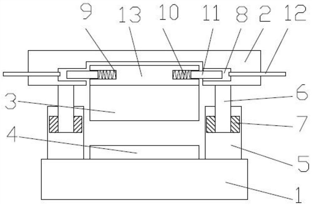
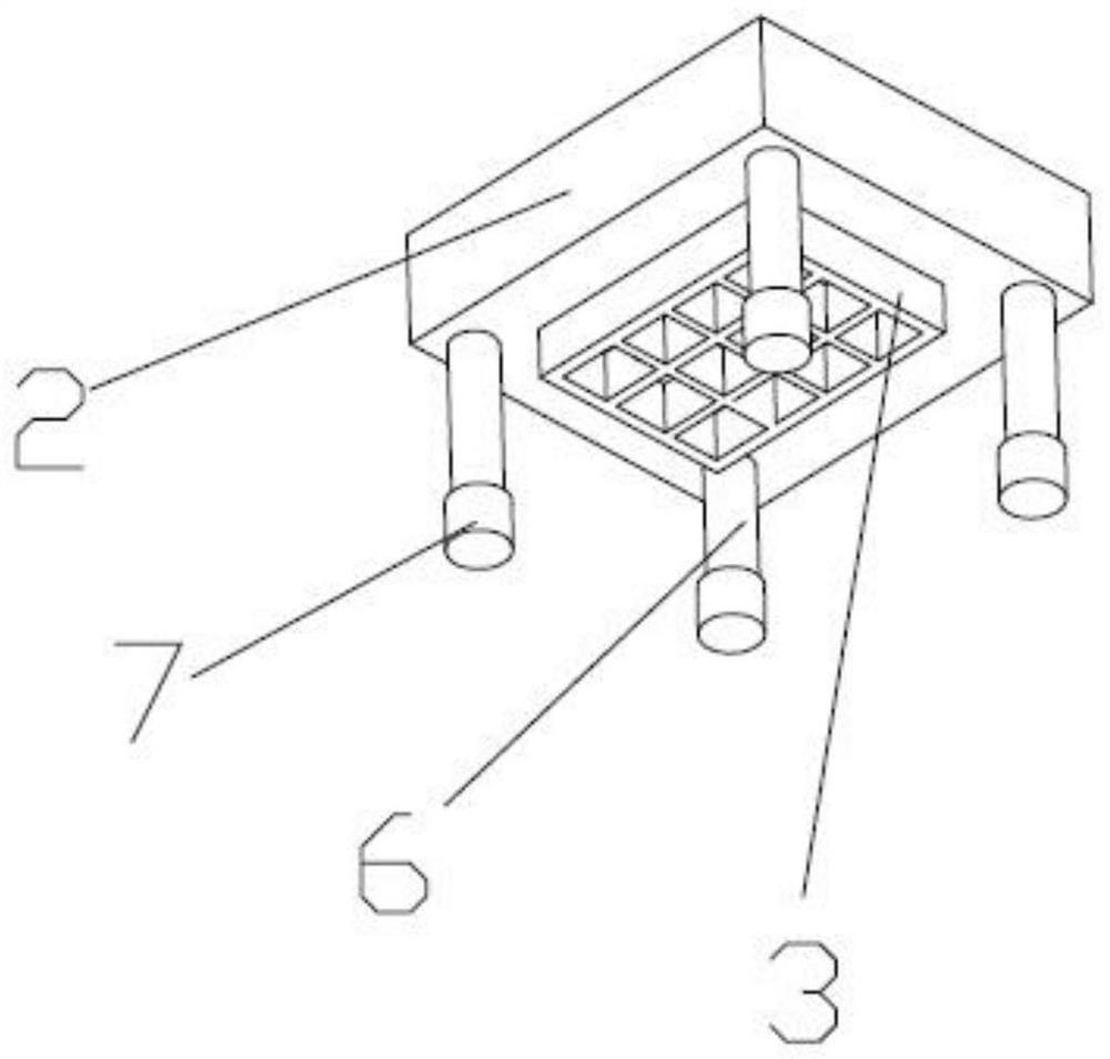
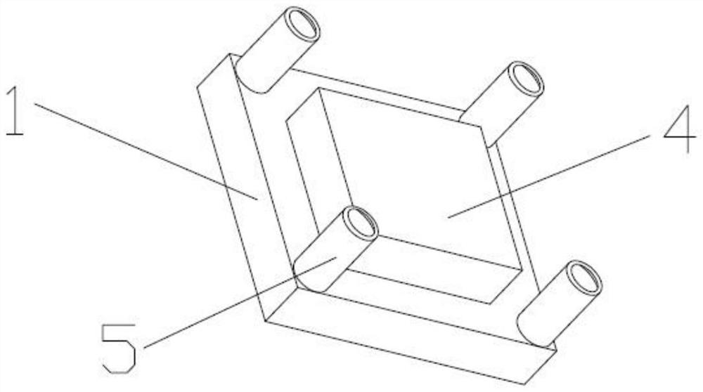
[0021] Such as figure 1 A cutting die for the continuous production of protective gear is shown, including a die die body and a fixing plate 2 for fixing the die die body, a cutting groove 14 is arranged on the die die body, and a die die is arranged below the cutting groove 14 The mounting seat 13, the cutting groove 14 is provided with a ejector device, the ejector device is provided with a spring inside, and the ejector device is used to eject the object to be cut; The pin 11 is fixed in the slot 8, the fixed plate 2 is provided with the slot 8, the pin 11 is arranged in the first groove 9 of the die mounting seat 13, and the inside of the first gr...


PUM


Abstract

The invention discloses a cutting die for continuous production of protectors. The cutting die comprises a cutting die body and a fixing plate for fixing the cutting die body, wherein a cutting groove is formed in the cutting die body, a cutting die mounting seat is arranged below the cutting groove, an ejection device is arranged in the cutting groove, and the ejection device is used for ejecting a cut object; and the cutting die and the fixing plate are fixed through a clamping pin and a clamping groove, the clamping groove is formed in the fixing plate, the clamping pin is arranged in a first groove of the cutting die mounting seat, a fixing rod is further arranged on the fixing plate, a piston is arranged on the fixing rod, a base is arranged below the mounting seat, an air cylinder is arranged on the base, the fixing rod is placed in the air cylinder to be fixed, the air cylinder is filled with gas, a port of the air cylinder is sealed, and a cutting workbench is further arranged on the base. The cutting die has the advantage of being capable of achieving continuous machining.

Description

technical field [0001] The invention relates to the technical field of cutting dies, in particular to a cutting die used for continuous production of protective gear. Background technique [0002] Knife dies are relatively commonly used products in the die-cutting industry. They are generally used to punch out the shape of the required die-cut products. They are generally used in printing and packaging, plastic packaging, leather, toys, automobiles and other industries. [0003] After cutting with the existing ordinary engraving knife die, the cut waste needs to be cleaned manually to achieve secondary cutting, especially for the parts with small blade gaps. Waste cleaning is time-consuming and labor-intensive. When cutting hard materials At the same time, when cleaning the jammed material, it will also cause the cutting edge to jump and the edge to be cut, which cannot meet the processing requirements, resulting in serious waste of raw materials and reducing work efficiency...

Claims


Application Information

Patent Timeline
Patent Type & Authority Applications(China)
IPC IPC(8): B26F1/44B26D7/26B26D7/18
CPCB26F1/44B26D7/2614B26D7/1818
Inventor 郜泽群
Owner 扬州市品冠体育用品有限公司
Why Eureka
Try Eureka