
Automatic pressing and stacking forming device for spiral ribs

A technology of forming device and spiral rib, applied in decorative arts, embossed decorative parts, etc., can solve the problems of cumbersome process and reduce the coding efficiency of spiral rib, and achieve the effect of speeding up coding efficiency and reducing labor intensity.

Pending Publication Date: 2021-06-11
安徽伟豪预应力设备有限公司
View PDF7 Cites 0 Cited by
  • Summary
  • Abstract
  • Description
  • Claims
  • Application Information

AI Technical Summary

Problems solved by technology

[0003] In the production of spiral bars, in order to ensure that the manufacturer and production quality of the spiral bars can be traced, it is necessary to code the side walls of the spiral bars before bending, so that the batch numbers of the spiral bars after production are different, and then the The manufacturer and quality of spiral bars are traced back. At present, the coding of spiral bars is done by manually putting the steel bars into the coding groove, and then pressing the steel bars to make the codes on the steel bars successful. This makes the whole process cumbersome and reduces the cost. Coding efficiency of spiral ribs

Method used

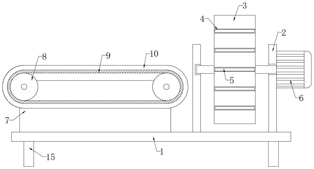
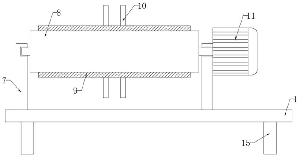
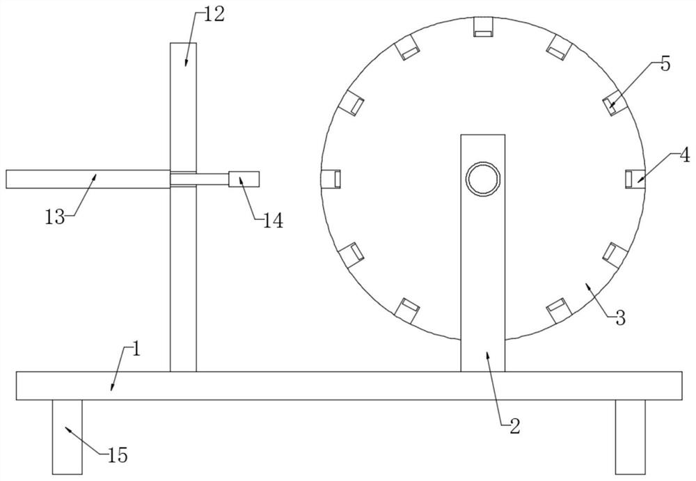

Image

  • Automatic pressing and stacking forming device for spiral ribs
  • Automatic pressing and stacking forming device for spiral ribs
  • Automatic pressing and stacking forming device for spiral ribs

Examples


Embodiment Construction

[0020] The following will clearly and completely describe the technical solutions in the embodiments of the present invention with reference to the accompanying drawings in the embodiments of the present invention. Obviously, the described embodiments are only some, not all, embodiments of the present invention.

[0021] In describing the present invention, it should be understood that the terms "upper", "lower", "front", "rear", "left", "right", "top", "bottom", "inner", " The orientation or positional relationship indicated by "outside", etc. is based on the orientation or positional relationship shown in the drawings, and is only for the convenience of describing the present invention and simplifying the description, rather than indicating or implying that the referred device or element must have a specific orientation, so as to Specific orientation configurations and operations, therefore, are not to be construed as limitations on the invention.

[0022] refer to Figure ...


PUM


Abstract

The invention discloses an automatic pressing and stacking forming device for spiral ribs. The automatic pressing and stacking forming device for the spiral ribs comprises a base; two first vertical plates are symmetrically and fixedly connected to the upper end of the base; a circular disc is rotationally connected to the side walls, close to each other, of the two first vertical plates through a rotating shaft; a plurality of through grooves are evenly formed in the side walls of the circular disc in the circumferential direction of the circular disc; character dies are fixedly connected to the inner walls of the multiple through grooves; a first motor is fixedly connected to the side wall of one first vertical plate; the movable end of the first motor is fixedly connected with one end of a rotating shaft; an extrusion mechanism for extruding the spiral rib is mounted on the base; and two second vertical plates are symmetrically and fixedly connected to the upper end of the base. According to the automatic pressing and stacking forming device for the spiral ribs, a steel bar is placed in an annular belt, then a second motor is driven to rotate, the second motor drives two rollers to rotate, a conveying belt moves on the side walls of the two rollers, then the steel bar is conveyed into the through grooves, and therefore, manual conveying is not needed, the labor intensity is reduced, and the code printing efficiency of the spiral bar is improved.

Description

technical field [0001] The invention relates to the technical field of spiral rib production, in particular to a spiral rib automatic pressure code forming device. Background technique [0002] Spiral tendons generally refer to spiral stirrups, which are architectural terms, referred to as spiral stirrups. In reinforced concrete structures, the single stirrups in beams, columns, piles and other strip members are made into a continuous shape, which is called spiral stirrups. [0003] In the production of spiral bars, in order to ensure that the manufacturer and production quality of the spiral bars can be traced, it is necessary to code the side walls of the spiral bars before bending, so that the batch numbers of the spiral bars after production are different, and then the The manufacturer and quality of spiral bars are traced back. At present, the coding of spiral bars is done by manually putting the steel bars into the coding groove, and then pressing the steel bars to mak...

Claims


Application Information

Patent Timeline
Patent Type & Authority Applications(China)
IPC IPC(8): B44B5/00B44B5/02
CPCB44B5/0076B44B5/024B44B5/02
Inventor 蔡维好
Owner 安徽伟豪预应力设备有限公司
Learn More