Filtration and washing equipment

A filter device and washing equipment technology, applied in the field of clothing cleaning, can solve the problems of low flow rate, low filtration efficiency, and unstable direction of the filter cover, and achieve the effect of increased flow, high filtration efficiency, and avoiding entanglement of clothes

Active Publication Date: 2022-04-12
WUXI LITTLE SWAN ELECTRIC CO LTD
View PDF4 Cites 0 Cited by
  • Summary
  • Abstract
  • Description
  • Claims
  • Application Information

AI Technical Summary

Problems solved by technology

[0002] Existing washing equipment includes a cylinder body with a washing chamber, a pulsator located in the washing chamber and a filter cover plate arranged on the circumferential side wall of the cylinder body. When the pulsator rotates, it drives the water in the washing chamber to enter the filter cover plate. The filter cover is located on the side wall of the cylinder, the flow rate entering the filter cover is low and the direction is unstable, and the filtration efficiency is low

Method used


Image

  • Filtration and washing equipment
  • Filtration and washing equipment
  • Filtration and washing equipment

Examples


Embodiment Construction

[0045] It should be noted that, in the case of no conflict, the embodiments in the application and the technical features in the embodiments can be combined with each other. Undue Limitation of This Application.

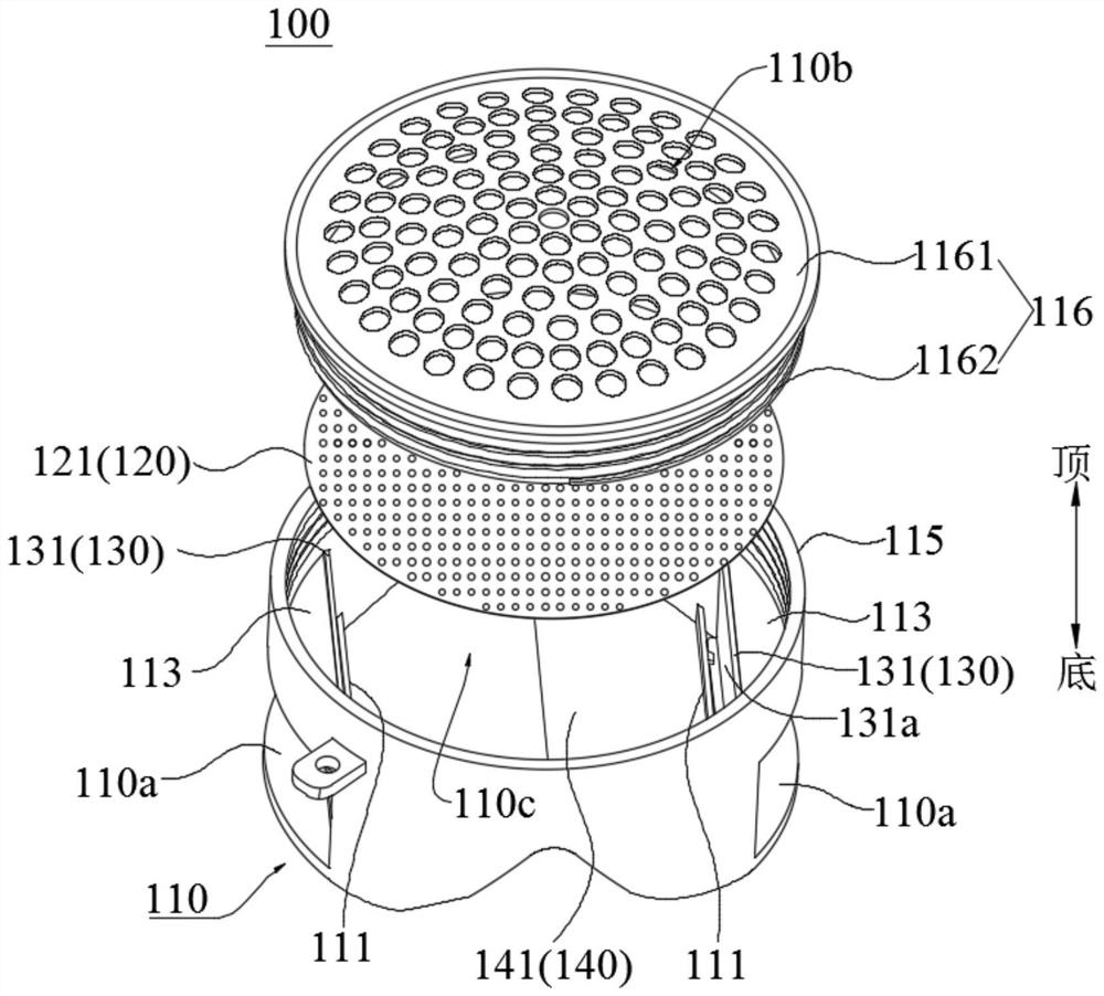
[0046] In the description of this application, the orientation or positional relationship of "top", "bottom", "upper" and "lower" refers to the orientation or positional relationship shown when the filter device and washing equipment are in normal use, for example figure 1 It should be understood that these orientation terms are only for the convenience of describing the application and simplifying the description, rather than indicating or implying that the referred device or element must have a specific orientation, be configured in a specific orientation and operation, and therefore should not be construed as limiting the application.

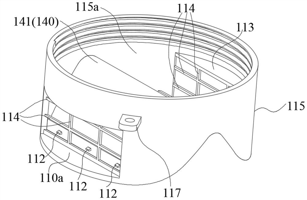
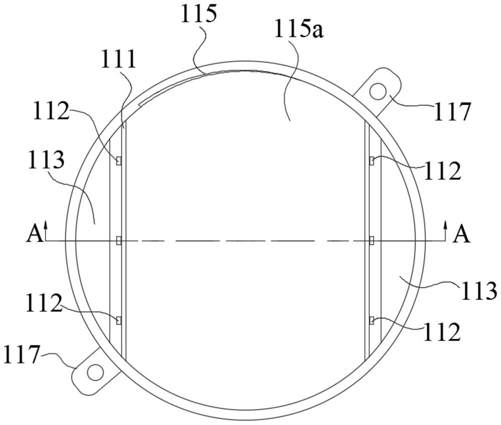
[0047] See Figure 1 ~ Figure 4 On the one hand, the embodiment of the present application provides a filtering device for wash...


PUM


Abstract

An embodiment of the present application provides a filtering device and washing equipment. The filtering device includes a housing, a filtering structure and a one-way control structure. The housing is used to connect with the pulsator of the washing equipment. The housing is formed with a water inlet along the rotational direction of the pulsator. A water outlet is formed on the top of the shell, and the water inlet and the water outlet are used to communicate with the washing chamber of the washing equipment. A filter chamber is formed in the shell to communicate with the water inlet and the water outlet; the filter structure is arranged in the filter chamber; the one-way control structure is arranged in the At the water inlet, the one-way control structure controls the liquid to flow into the filter chamber from the water inlet in one direction; because the flow rate of the liquid flowing through the filter device is faster, the flow rate of the liquid increases and the filtration efficiency is higher.

Description

technical field [0001] The present application relates to the technical field of clothes cleaning, in particular to a filtering device and washing equipment. Background technique [0002] Existing washing equipment includes a cylinder body with a washing chamber, a pulsator located in the washing chamber and a filter cover plate arranged on the circumferential side wall of the cylinder body. When the pulsator rotates, it drives the water in the washing chamber to enter the filter cover plate. The filter cover is located on the side wall of the cylinder, the flow rate entering the filter cover is low and the direction is unstable, and the filtration efficiency is low. Contents of the invention [0003] In view of this, the embodiment of the present application expects to provide a filtering device and washing equipment with high filtering efficiency. In order to achieve the above purpose, [0004] On the one hand, the embodiment of the present application provides a filter...

Claims


Application Information

Patent Timeline
Patent Type & Authority Patents(China)
IPC IPC(8): D06F39/10D06F17/06
CPCD06F39/10D06F17/06
Inventor 喻光安付仕波朱彪薛欣洋
Owner WUXI LITTLE SWAN ELECTRIC CO LTD
Why Eureka
Try Eureka