Rigid connection joint of rectangular steel beam and H-shaped steel column and construction method

A technology of rigid connection and rectangular steel pipe, which is applied in construction, building structure, and construction material processing, etc., can solve the problems of rigid bolt connection, complex connection structure, technical difficulty, etc., and achieve convenient docking positioning and convenient installation Effect

Inactive Publication Date: 2021-06-15
COLLEGE OF SCI & TECH NINGBO UNIV
View PDF0 Cites 0 Cited by
  • Summary
  • Abstract
  • Description
  • Claims
  • Application Information

AI Technical Summary

Problems solved by technology

[0005] (1) It is difficult to rigidly connect the rectangular steel beam and the H-shaped cross-section steel column through bolts
[0006] (2) The connection structure is too complex and the technical difficulty of on-site construction is relatively large

Method used


Image

  • Rigid connection joint of rectangular steel beam and H-shaped steel column and construction method
  • Rigid connection joint of rectangular steel beam and H-shaped steel column and construction method
  • Rigid connection joint of rectangular steel beam and H-shaped steel column and construction method

Examples


Embodiment 1

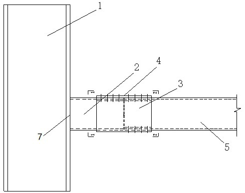
[0043] as attached figure 1 As shown, a rigid connection node between a rectangular steel beam and an H-shaped steel column provided for an embodiment of the present invention includes:

[0044] The first piece 1; the first piece 1 is an H-shaped steel column;

[0045] The second number 2; the second number 2 includes a first area and a second area; the first area is used to be fixedly connected to the first number 1 by welding;

[0046] The third part 3; the third part 3 is channel steel, including the third area and the fourth area; the third area is used to cover the second area, and is fixedly connected with the second area by welding; The fourth area is used to cover the fifth area of ​​the fifth part 5;

[0047] The fifth part 5; the fifth part 5 is a rectangular steel beam, including the fifth area and the sixth area;

[0048] The fourth part 4; the fourth part 4 is a rectangular steel plate; when the fourth area is used to cover the fifth area of ​​the fifth part 5,...

Embodiment 2

[0067] An embodiment of the present invention also provides a construction method for a rigid connection node between a rectangular steel pipe beam and an H-shaped steel column, comprising the following steps:

[0068] Covering the second area of ​​the second number 2 with the third area of ​​the third number 3, and making the third area and the second area fixedly connected by welding;

[0069] Welding connects the first area of ​​the second part 2 and the first part 1;

[0070] Cover the fifth area of ​​the fifth item 5 with the fourth area of ​​the third item 3;

[0071] Put the fourth part 4 on the outside of the third part 3, and fix the third part 3, the fourth part 4 and the fifth part 5 by bolts.

[0072] In this embodiment, the first piece 1 (that is, the H-shaped steel column) and the fifth piece 5 (that is, the rectangular steel beam) form a rigid connection node by using the second piece 2 and the third piece 3 as intermediate pieces The basic form is finally rig...


PUM


Abstract

The invention relates to the technical field of structural engineering, and provides a rigid connection joint of a rectangular steel beam and an H-shaped steel column. The rigid connection joint comprises a first piece, a second piece, a third piece, a fourth piece and a fifth piece. The first piece is the H-shaped steel column. The second piece is included. The third piece is channel steel. The fifth piece is the rectangular steel beam. The fourth piece is a rectangular steel plate. The second piece and the third piece serve as middle pieces to enable the first piece and the fifth piece to form a basic form of the rigid connection joint, and finally the basic form is rigidly fixed through the fourth piece and a bolt, so that the problem that rigid connection between the rectangular steel beam and the H-shaped section steel column is difficult through the bolt is solved. The rigid connection joint has the advantages that butt joint positioning between the rectangular steel beam and the H-shaped section steel column is facilitated, mounting is quite convenient and the like, and support is provided for development of fabricated steel structure buildings. The invention further provides a construction method of the rigid connection joint of the rectangular steel tube beam and the H-shaped steel column.

Description

technical field [0001] The invention belongs to the technical field of structural engineering, and in particular relates to a rigid connection node between a rectangular steel beam and an H-shaped steel column and a construction method. Background technique [0002] In recent years, the development of prefabricated steel structure building technology has received widespread attention from the central government, local governments at all levels and all walks of life. For steel frame structures, the structural system is basically mature, but the development of a series of on-site installations that are easy to install and the rigid connection of various cross-section steel beams and steel columns through bolts has become a hot spot in the development of steel structure prefabricated building technology. [0003] In actual engineering, when the closed rectangular tube is used as a wall beam, it needs to be rigidly connected with the H-shaped cross-section steel column to meet t...

Claims


Application Information

Patent Timeline
Patent Type & Authority Applications(China)
IPC IPC(8): E04B1/58E04B1/24E04G21/14
CPCE04B1/2403E04B1/5812E04B1/5831E04B2001/2406E04G21/14
Inventor 王新堂王占良
Owner COLLEGE OF SCI & TECH NINGBO UNIV
Why Eureka
Try Eureka