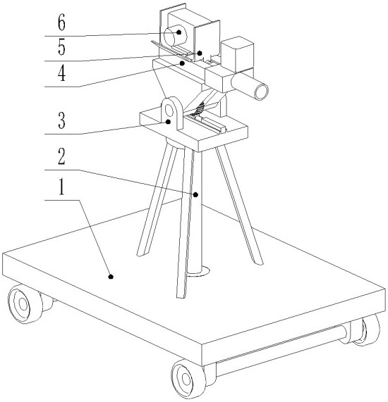
Extreme shooting ejection photography support
A technology of photographic bracket and ejection device, which is applied in the direction of machine/bracket, supporting machine, spring/shock absorber, etc., can solve the problems of tipping, breaking the camera, unable to guarantee the safety of the camera and lens, etc., and achieve the effect of ensuring safety.
- Summary
- Abstract
- Description
- Claims
- Application Information
AI Technical Summary
Problems solved by technology
Method used
Image

Examples
Embodiment Construction
[0029] The technical solutions of the present invention will be further specifically described below through the embodiments and in conjunction with the accompanying drawings. In the following description, many specific details are set forth in order to fully understand the present invention, but the present invention can be implemented in many other ways different from those described here, and those skilled in the art can do similar Modifications, and therefore the present invention is not limited to the specific examples disclosed below. In the description of the present invention, it should be noted that the orientation or positional relationship indicated by the terms "upper", "lower", "front", "back", "left", "right" etc. are based on the Orientation or positional relationship, or the orientation or positional relationship that the inventive product is usually placed in use, is only for the convenience of describing the present invention and simplifying the description, ...
PUM
 Abstract
Description
Claims
Application Information