Line support for municipal engineering

A line and engineering technology, applied in the municipal field, can solve the problems of increasing the force of the cable on the bracket, reducing the safety of the utility pole, and uneven force on the bracket, and achieving the effect of improving the safety.

Inactive Publication Date: 2021-06-15
李德水
View PDF0 Cites 0 Cited by
  • Summary
  • Abstract
  • Description
  • Claims
  • Application Information

AI Technical Summary

Problems solved by technology

[0003] Based on the above inventors' discovery, the existing line support for municipal engineering mainly has the following disadvantages, for example: due to the heavy weight of the cable, when it is suspended on the support, it will swing when it is blown by cross wind , and the inertia generated during the swing will increase the force of the cable on the bracket, making the force at both ends of the bracket uneven, causing the bracket to vibrate, causing the pole to shake with the vibration of the bracket, reducing the safety of the pole sex

Method used


Image

  • Line support for municipal engineering
  • Line support for municipal engineering
  • Line support for municipal engineering

Examples


Embodiment 1

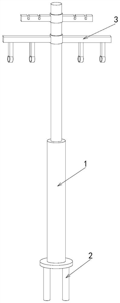
[0026] Example 1: Please refer to Figure 1-Figure 5 , the specific embodiments of the present invention are as follows:

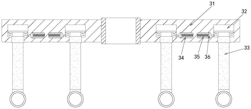
[0027] Its structure includes a utility pole 1, a base 2, and a line support 3. The bottom end of the utility pole 1 is provided with a base 2, and the line support 3 is located at the top of the utility pole 1. The line support 3 includes a support frame 31 , oil storage tank 32, wire loading device 33, movable groove 34, back-moving spring 35, oil push plate 36, described support frame 31 is provided with oil storage tank 32, and described oil storage tank 32 is connected with movable groove 34, and described wire loading The device 33 is engaged in the oil storage tank 32, the movable groove 34 is arranged at the side end of the oil storage tank 32, the return spring 35 is installed in the movable groove 34 transversely, and the oil pushing plate 36 is embedded in the end of the return spring 35 , the reset spring 35 and the oil push plate 36 are movab...

Embodiment 2

[0032] Example 2: Please refer to Figure 6-Figure 8 , the specific embodiments of the present invention are as follows:

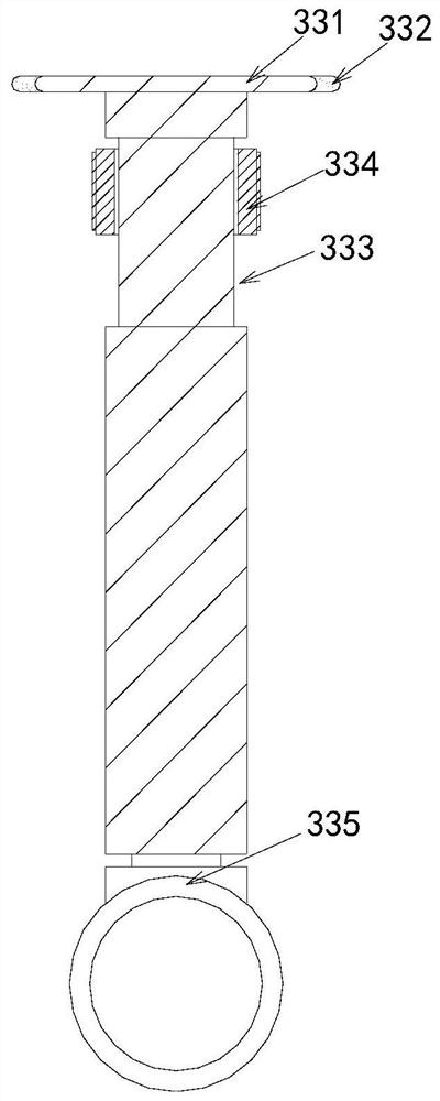
[0033] The clamping device 335 includes a mounting slot b1, a snapping head b2, a clamping frame b3, and a ball b4. The mounting slot b1 is arranged at the bottom of the wire loading device 33, and the snapping head b2 is snapped into the mounting slot. In the interior of b1, the clamping frame b3 is embedded in the bottom end of the engaging head b2, the four balls b4 are located at the upper and lower ends of the engaging head b2, and the balls b4 and the engaging head The active cooperation of b2 is beneficial to the contact between the ball b4 and the clamping head b2, thereby reducing the friction force on the clamping head b2, so that the clamping head b2 can drive the clamping frame b3 to rotate, so that it is easier for the staff to The cables are installed in the clamping frame b3.

[0034]The clamping frame b3 includes a clamping body b31, a fi...


PUM


Abstract

The invention discloses a line support for municipal engineering. The line support structurally comprises a telegraph pole, a base and a line support body; the base is arranged at the bottom end of the telegraph pole; the line support body is located at the top end of the telegraph pole; the line support body comprises a supporting frame, an oil storage groove, a line installing device, a movable groove, a reset spring and an oil pushing plate; the line installing device comprises a clamping block, a sealing block, a sliding groove, a limiting block and a line clamping device; the limiting block comprises a limiting body, a rubber pad, a supporting block and an iron sheet; and the iron sheet comprises a sealing sheet, a friction hole, a side sliding block and a cutting groove. According to the line support for municipal engineering of the invention, the oil pushing plate can squeeze hydraulic oil into the oil storage groove, so that the line installing device can move upwards, so that a cable arranged in the wire installing device can be buffered, shaking of the line support is avoided, shaking of the telegraph pole is avoided, and the safety of the telegraph pole is improved.

Description

technical field [0001] The invention relates to the field of municipal engineering, in particular to a line support for municipal engineering. Background technique [0002] In municipal engineering, the line bracket plays a very important role in the urban line layout planning. The bracket is fixed vertically on the ground, and the line is supported by the arm at the top of the bracket, so that the line can be hung neatly in the air to avoid clutter The lines placed in the air will affect the beauty of the road. [0003] Based on the above inventors' discovery, the existing line support for municipal engineering mainly has the following disadvantages, for example: due to the heavy weight of the cable, when it is suspended on the support, it will swing when it is blown by cross wind , and the inertia generated during the swing will increase the force of the cable on the bracket, making the force at both ends of the bracket uneven, causing the bracket to vibrate, causing the ...

Claims


Application Information

Patent Timeline
Patent Type & Authority Applications(China)
IPC IPC(8): H02G7/05H02G7/20
CPCH02G7/05H02G7/20
Inventor 骆秀英
Owner 李德水
Why Eureka
Try Eureka